

A thermal mass flow meter measures gas flow by observing how a moving gas removes heat from a heated sensing element. That makes the technology attractive for compressed air, nitrogen, natural gas, biogas, combustion air, and many other industrial gases. For the basic sensor physics, FlowT's explanation of how a thermal mass flow meter works covers the underlying heat-transfer principle. The more difficult question is how to preserve that measurement performance after the meter leaves the calibration bench.
Start by Understanding What the Accuracy Specification Means
Two thermal mass flow meters can both display an impressive accuracy statement and still offer very different performance at the flow rate that matters to your process. Before comparing numbers, identify how the specification is expressed.
Suppose a datasheet states an accuracy of ±1% of reading. At an indicated flow of 500 Nm³/h, the stated contribution is ±5 Nm³/h. Now consider a different instrument rated at ±0.5% of a 2,000 Nm³/h full scale. Its full-scale-based contribution is ±10 Nm³/h, including when the process is operating at 500 Nm³/h.
This does not mean one specification format is automatically better. It means the basis matters, especially when the meter spends most of its time well below maximum flow.
Accuracy, Repeatability and Uncertainty Are Not the Same Thing
Accuracy describes how close the reported flow is to an accepted reference. Repeatability describes how closely the instrument reproduces a result when the same conditions are repeated. A meter can repeat extremely well and still carry a systematic bias caused by an incorrect gas curve, wrong pipe diameter, or poor installation.
FlowT discusses this distinction further in its article on thermal mass flow meter repeatability.
Measurement uncertainty is broader. It considers the range of values that can reasonably be associated with the measurement result and may include contributions from calibration, reference equipment, repeatability, installation, gas properties, signal processing, and operating conditions. The existing FlowT discussion of thermal mass flow meter uncertainty provides additional background on intrinsic and application-related contributors.
When a project has a real accuracy requirement, do not ask only for "meter accuracy." Ask what accuracy or uncertainty applies at the minimum, normal, and maximum operating flow and under what stated gas and process conditions.
Gas Composition Is Part of the Measurement
Thermal mass measurement depends on heat transfer. Different gases have different thermal conductivity, specific heat, density, and viscosity, so they do not cool the heated sensor in exactly the same way.
This is why a meter calibrated for air should not automatically be treated as an equally accurate methane, hydrogen, carbon dioxide, or mixed-gas meter simply by changing a label in the transmitter.
For a pure gas with stable composition, the problem is relatively straightforward: select a meter and calibration appropriate for that gas. A known and stable mixture can also be handled when its composition is defined and the manufacturer has a suitable calibration or validated gas model.
A variable gas mixture requires more judgment. Consider a biogas process where the relative amounts of methane and carbon dioxide change with digestion conditions. A change from one composition to another alters the thermal properties seen by the sensor. The important question is not whether the transmitter can display "biogas"; it is whether the expected composition range remains compatible with the required measurement uncertainty.
FlowT's article on measuring gas mixtures with a thermal mass flow meter explains why mixture composition needs to be part of the application data.
A Practical Gas-Composition Decision Rule
- Single, stable gas: use a calibration intended for that gas whenever the accuracy requirement justifies it.
- Stable, known mixture: provide the complete mixture composition and confirm whether calibration is mixture-specific or based on a validated conversion.
- Mixture changes within a known range: provide normal, minimum, and maximum expected concentrations for the major components and ask how the stated error changes across that range.
- Composition changes widely or unpredictably: confirm whether thermal mass technology can still meet the required uncertainty before selecting it.
Pressure and Temperature Still Deserve Attention
One of the strongest reasons to use a thermal mass meter is that it can report mass flow without first measuring operating volume and then calculating density from separate pressure and temperature instruments. That advantage is sometimes shortened into the statement that pressure and temperature "do not affect" thermal mass measurement. That wording is too broad.
The sensor still operates inside a real gas at a real pressure and temperature. Those conditions can influence gas properties, heat transfer, sensor temperature limits, and the relationship between the process and the original calibration. The magnitude and importance of the effect depend on the gas, meter design, calibration method, and operating range.
FlowT has a separate technical discussion of gas pressure fluctuations in thermal mass measurement. For projects with unusually high pressure, broad temperature swings, or tight uncertainty requirements, include those conditions in the application review rather than assuming the standard calibration automatically covers them.
Low Flow, Flow Regime and the Useful Measuring Range
Thermal technology is often selected because it can detect relatively low gas flow without placing a major restriction in the line. That does not mean every meter has identical accuracy from zero to maximum flow.
At different Reynolds numbers and velocity ranges, the local flow pattern and heat-transfer relationship can change. Very low flow can also make zero stability and sensor offsets more significant as a percentage of the measured value.
This is why the useful question is not simply, "What is the turndown ratio?" Ask what error specification applies near the actual minimum operating point. FlowT's discussion of thermal mass measurement accuracy in laminar flow is relevant when the application operates near the lower end of the velocity range.
Moisture, Condensation and Sensor Fouling Produce Different Errors
Humidity in a gas and liquid water contacting the sensor are not the same condition. Water vapor is part of the gas mixture. Condensate forms a liquid phase that transfers heat very differently and can cause a sudden change in sensor response.
Contamination can be more gradual. Compressor oil, dust, process residue, or fine particles can build a coating on the sensing element. A slowly developing coating changes the thermal path between the sensor and the gas and may look like calibration drift.
That difference is useful during troubleshooting. A reading that changes suddenly after a separator failure or condensation event suggests a different investigation from a meter that has drifted gradually over months in a dirty gas stream.
Before recalibrating a meter with unexplained drift, review:
- gas composition changes;
- dew point and condensation history;
- compressor oil carryover;
- dust or particulate loading;
- sensor cleanliness;
- changes to upstream filters or separators;
- recent process maintenance.
Installed Accuracy Depends on the Flow Profile
A thermal insertion sensor does not physically measure every point across a large pipe. It senses conditions at its installed location and the instrument uses that measurement together with the configured pipe geometry and calibration model to calculate total flow.
An elbow, tee, reducer, control valve, blower outlet, compressor discharge, or partially closed valve can create swirl and asymmetric velocity profiles. A meter installed in that disturbed profile may be very repeatable while still reporting a biased total flow.
Straight-run guidance is therefore important, but a single universal number should not be applied to every installation. The required upstream and downstream length depends on the meter design and the disturbance. The selected product documentation should govern the final layout.
Probe Position Is a Configuration Issue as Well as a Mechanical Issue
Insertion depth, orientation, and the configured internal pipe diameter all matter. Entering the nominal pipe size when the transmitter requires actual internal diameter can introduce a systematic area calculation error. A probe installed too shallow or too deep can sample a different part of the velocity profile than intended.
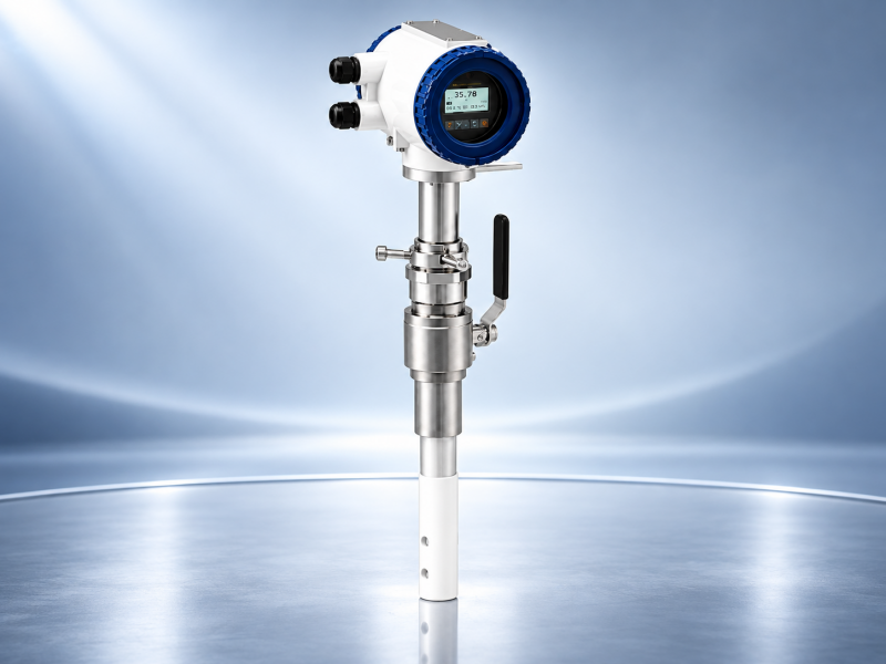
For larger existing pipelines, an insertion thermal mass flow meter can reduce piping modification, but the installation needs enough information about pipe geometry and upstream conditions to make the measurement meaningful.
Smaller lines may benefit from a defined inline measuring section. FlowT compares the engineering trade-offs in its inline versus insertion thermal mass flow meter comparison.
Calibration: Actual Gas, Surrogate Gas and What the Certificate Should Show
Calibration connects the electrical response of the sensor to a known reference flow. For thermal meters, gas selection matters because heat transfer is gas-dependent.
ISO 14511:2019 specifically addresses the specification, testing, inspection, installation, operation, and calibration of thermal mass gas flowmeters used for gases and gas mixtures.
Where practical and justified by the application, actual-gas calibration provides the closest representation of the real thermal properties. In other cases, manufacturers may use air, nitrogen, or another surrogate gas and apply an equivalency model. A surrogate approach can be appropriate, but users should understand how the conversion was established and what additional uncertainty applies.
The ISA article on calibrating thermal mass flowmeters discusses the limitations that can arise when theoretical gas equivalency does not reproduce the actual heat-transfer behavior of the process gas.
What to Request With a Calibration
- the calibration gas or surrogate gas;
- the tested minimum and maximum flow;
- individual calibration points across the operating range;
- reference temperature and pressure conditions;
- the measurement units and standard-volume basis;
- reference equipment and traceability;
- stated calibration uncertainty;
- repeatability information where relevant;
- as-found and as-left results for recalibration work;
- any gas correction or equivalency method applied.
For general flowmeter calibration terminology and traceability, FlowT's flow meter calibration technical overview provides useful background.
If an accredited laboratory is specified by the project, confirm that the laboratory's accredited scope covers the relevant measurement and flow range. ISO/IEC 17025 defines competence, impartiality, and consistent-operation requirements for testing and calibration laboratories.
Do Not Confuse Mass Flow With Standard Volume
Thermal meters are commonly called direct mass flow instruments, yet many plants display results in Nm³/h, Sm³/h, SCFM, or SLPM rather than kg/h. Those are standardized volumetric quantities, not physical volume at the actual pipeline pressure and temperature.
The distinction matters when a thermal meter is compared with compressor data, a utility report, a PLC calculation, or another flow technology. The systems need to use the same reference temperature, pressure, and gas definition.
FlowT's mass flow versus volume flow explanation covers the physical difference, while its overview of flow units including kg/h and Nm³/h is useful when checking transmitter and PLC configuration.
A Practical Installed-Error Diagnostic Table
| Observed Problem | Likely Causes | First Checks | Next Action |
|---|---|---|---|
| Reading is consistently high or low | Wrong gas curve, incorrect pipe ID, biased flow profile, gas composition mismatch | Configuration, gas data, pipe dimensions, upstream layout | Correct configuration and compare against a reference before changing calibration |
| Reading is stable but does not match another meter | Different reference conditions, technology differences, installation bias, calibration mismatch | Units, standard conditions, gas basis, calibration certificates | Put both measurements on the same basis before diagnosing the sensor |
| Reading fluctuates rapidly | Pulsating flow, electrical noise, condensate, unstable process conditions | Process trend, wiring, grounding, moisture conditions | Separate process instability from meter instability |
| Reading drifts slowly over time | Sensor fouling, composition change, process residue, long-term calibration shift | Sensor condition and process history | Clean or inspect as permitted, then verify against a reference |
| Low-flow reading is poor but normal flow is acceptable | Operation near lower useful range, zero offset, flow regime effects | Minimum calibrated point and actual normal flow | Review sizing or low-range calibration requirements |
When Thermal Mass Is the Right Technology-and When It Is Not
Thermal mass technology is particularly useful when the gas composition is known, pressure loss should be low, the application benefits from low-flow sensitivity, and direct gas mass or standard-volume measurement is useful.
A gas mass flow meter can be a good fit for industrial gas distribution, nitrogen, combustion gas, and similar clean-gas duties. For plant compressed-air monitoring, an air mass flow meter can provide consumption data without a separate density-compensation system. Applications with different gas types can also be reviewed against a thermal mass flow meter for industrial gas measurement, provided the gas and operating limits are confirmed.
Thermal mass is not the automatic answer to every gas application.
| Application Condition | Thermal Mass | Vortex | Coriolis |
|---|---|---|---|
| Clean gas, low pressure loss important | Strong candidate | Possible depending on velocity and process | Possible but often higher cost and pressure drop |
| Very low gas flow | Often attractive | May be limited by minimum Reynolds number or velocity | Depends strongly on meter size and application |
| Widely changing gas composition | Requires careful evaluation | May still require density or compensation depending on output | Can provide direct mass measurement without thermal gas-property calibration |
| Wet or heavily contaminated gas | Potential fouling or condensation concern | Application-dependent | Application-dependent |
| Steam | Generally not the standard choice | Common industrial option | Application-dependent and less common |
The purpose of this comparison is not to rank technologies universally. It is to identify where the measurement principle itself fits the process. FlowT also provides a broader comparison between thermal mass and other flow meter technologies for applications where the technology has not yet been selected.
Thermal Mass Flow Meter Selection Checklist
A good quotation request should contain enough process information for the meter to be sized and calibrated for the real operating condition. At minimum, prepare:
- Gas: exact gas name or full composition of the mixture.
- Composition range: expected variation in major gas components.
- Flow: minimum, normal, and maximum flow rather than maximum only.
- Units: kg/h, Nm³/h, Sm³/h, SCFM, or another required output.
- Reference conditions: standard temperature and pressure used for standard-volume reporting.
- Pressure: normal, minimum, and maximum operating pressure.
- Temperature: normal and extreme gas temperature.
- Gas condition: humidity, possible condensation, oil carryover, dust, or process contaminants.
- Pipe: material, schedule, actual internal diameter, and orientation.
- Installation: available straight run and nearby elbows, valves, reducers, compressors, or blowers.
- Performance: required uncertainty or accuracy at the actual normal and minimum flow.
- Calibration: actual-gas requirement, surrogate-gas acceptance, certificate, and traceability needs.
- Output: 4–20 mA, pulse, RS485/Modbus, HART, alarm, or totalizer.
- Environment: enclosure, hazardous-area approval, ambient temperature, and material requirements.
Frequently Asked Questions
What is a typical thermal mass flow meter accuracy?
There is no single value that should be applied to every thermal mass meter. Accuracy depends on the model, specification basis, calibrated range, gas, installation, and operating conditions. Compare the exact datasheet statement at your normal and minimum flow rather than relying on a generic technology-level number.
Does gas pressure affect a thermal mass flow meter?
Thermal mass measurement does not normally require a separate pressure transmitter to calculate mass flow from operating volume, but pressure can still influence gas properties and the relationship between process conditions and calibration. High-pressure or widely varying-pressure applications should be reviewed against model-specific calibration data.
Can a thermal mass flow meter measure a changing gas mixture?
Possibly, but the required accuracy determines whether it is practical. Provide the expected composition range and ask how the meter's calibration or gas model performs across that range. Large or unpredictable composition changes may justify a different measurement approach.
Should a thermal mass flow meter be calibrated with the actual gas?
Actual-gas calibration is the closest representation of the process gas when it is feasible and justified. Surrogate-gas calibration can also be used, but the user should understand the equivalency method and additional uncertainty associated with transferring the calibration between gases.
Why can a thermal mass flow meter be repeatable but still inaccurate?
Repeatability only shows that the meter reproduces the same result under repeated conditions. An incorrect gas curve, pipe diameter, probe position, or disturbed flow profile can create a stable systematic bias that repeats very well.
How much straight pipe does a thermal mass flow meter require?
The answer depends on the specific meter and the upstream disturbance. An elbow, two elbows, a control valve, reducer, compressor, or blower can create different flow profiles. Use the installation requirements for the selected model instead of applying one universal straight-run value.
How do I know whether the sensor needs cleaning or recalibration?
Review the failure pattern first. Gradual drift in a contaminated process may justify sensor inspection before calibration. If the sensor is clean and configuration, gas composition, flow profile, and process conditions are unchanged, reference verification or recalibration becomes a more logical next step.
Is an insertion or inline thermal mass flow meter better?
Neither is universally better. Inline meters provide a defined flow section and are convenient for many smaller lines. Insertion meters are attractive for larger pipes and retrofits but depend more heavily on correct pipe dimensions, probe position, and the developed flow profile.
Final Takeaway
Thermal mass flow meter accuracy should be treated as an installed measurement-system question, not just a catalog number. Start with the accuracy basis and operating range. Then verify the gas composition, pressure and temperature range, moisture and contamination risk, flow profile, probe position, reporting units, and calibration method.
If an installed meter disagrees with another measurement, do not change a calibration factor immediately. First make sure both systems use the same flow units and reference conditions, then check gas composition, configuration, sensor condition, pipe geometry, and installation. Calibration should confirm a correctly applied meter, not hide an application problem.
For new projects, the quality of the application data usually determines the quality of the final meter selection. Providing the real gas composition, minimum and normal flow, process conditions, pipe details, accuracy requirement, and calibration expectations gives the supplier enough information to determine whether thermal mass technology is appropriate and how the meter should be configured for the job.


