

This principle is most commonly associated with the rotameter. It is mechanically simple, easy to read, and useful for many low-to-moderate flow applications. However, a correct reading depends on more than float height: fluid density, viscosity, gas pressure and temperature, installation orientation, scale units, and calibration conditions can all matter. For a broader view of meter selection, see this flow measurement and sizing guide.
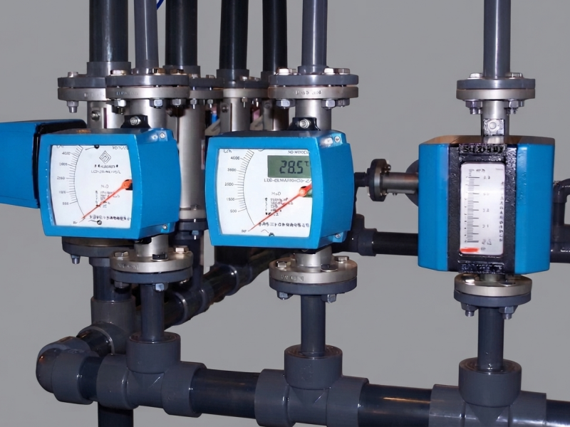
What Is a Variable Area Flow Meter?
A conventional variable area flow meter has four basic elements: a tapered measuring tube, a freely moving float, a scale or indicator, and process connections. The tube is narrower at the bottom and wider at the top. As the float moves upward, the gap between the float and tube wall increases.
That changing gap explains the name variable area. KROHNE describes the classic design as an upright tapered tube in which the float forms an annular gap whose area changes with float position. KROHNE's variable area flowmeter principle also identifies gravity, buoyancy or lifting force, and flow force as the main forces acting on the float. :contentReference[oaicite:1]{index=1}
The term rotameter is commonly used for this tapered-tube, float-type instrument. In practice, designs may use glass, plastic, or metal measuring tubes, and some industrial models transmit float position to an external indicator instead of relying on direct visual reading.
How Does a Variable Area Flow Meter Work?
1. Fluid Enters the Meter
In a conventional gravity-based rotameter, the fluid enters from the bottom and flows upward around the float. With no flow, gravity keeps the float near the lower end of the tube.
2. Flow Creates an Upward Force
As flow increases, the moving fluid produces an upward force on the float. Buoyancy also acts upward, while the float's weight acts downward.
3. The Float Rises Into a Wider Section
When the upward forces exceed the effective downward force, the float rises. Because the tube becomes wider toward the top, the annular passage around the float becomes larger.
4. A New Force Balance Is Reached
The float settles when the forces reach equilibrium. Conceptually:
Float weight = buoyancy + flow-induced upward force
The exact relationship depends on float geometry, fluid properties, and the meter's calibration. This is why the instrument should be treated as a calibrated measuring device rather than a simple "floating ball in a tube."
5. Float Position Is Converted to Flow Rate
The stable float position corresponds to a value on the calibrated scale or external indicator. Higher flow normally produces a higher float position and a larger available flow area.
Variable area meters are often described as approximately constant differential-pressure devices because the float moves to change the flow area instead of keeping the restriction fixed. In real service, however, the pressure relationship is not perfectly constant under every condition. If pressure behavior is important to the application, the broader relationship between flow rate and pressure should be considered together with the meter manufacturer's data.
What Can Change the Reading?
The operating principle is simple; the interpretation of the reading is where many errors occur.
| Factor | Why It Matters | What to Check |
|---|---|---|
| Fluid density | Changes buoyancy and the force balance | Calibration fluid and operating density |
| Viscosity | Changes flow behavior around the float | Liquid properties and manufacturer limits |
| Gas pressure | Changes gas density | Calibration pressure and actual absolute pressure |
| Temperature | Can change density and viscosity | Calibration temperature and process temperature |
| Orientation | Changes the gravity relationship in conventional designs | Required installation position |
| Deposits or contamination | Can restrict free float movement | Tube and float cleanliness |
Gas Service Requires Particular Care
A gas scale is not automatically transferable from one gas or operating condition to another. Pressure should also be handled correctly: gas correction calculations use absolute pressure, not simply gauge pressure. If PSIA, PSIG, and PSI are easy to confuse, this PSI, PSIA, and PSIG guide provides the distinction.
Brooks Instrument publishes gas correction guidance for variable area meters and notes that its simple correction factors are approximate and may become inaccurate at very low flow or elevated pressure. Its pressure and temperature correction guidance also specifies absolute pressure and absolute temperature. Brooks Instrument's variable area gas correction guide is a useful reference when operating conditions differ from the original calibration. :contentReference[oaicite:2]{index=2}
It is also important to know whether the scale represents volumetric flow or a standardized gas flow unit. If the distinction is unclear, review mass flow versus volume flow and the common flow meter units used in industry before comparing readings.
Liquid Service Is Not Immune to Fluid-Property Changes
For liquids, density and viscosity can affect the relationship between float position and actual flow. Brooks also publishes a liquid-density correction method and warns that a meter may not remain suitable if the new fluid's specific gravity differs greatly from the original application. Brooks Instrument's liquid-density correction note illustrates why a different process liquid may require correction or a different meter. :contentReference[oaicite:3]{index=3}
When measurement traceability matters, treat correction and calibration as separate issues. A correction estimates how a known meter responds under changed conditions; calibration establishes the relationship between the instrument indication and a reference. For more context, see the site's guide on how to calibrate a flow meter and its overview of liquid flow meter calibration methods and traceability.
How to Read a Rotameter Correctly
Do not assume that every float is read at the same point. The correct reference depends on the float geometry and the manufacturer's scale design. For example, Yokogawa specifies the top of the float as the reading point on its RAGN and RAGL designs. Yokogawa's RAGL documentation also specifies vertical installation with upward flow for that design. :contentReference[oaicite:4]{index=4}
- Confirm the specified float reading point before using the scale.
- Read the scale at eye level to reduce parallax error on transparent tubes.
- Check the engineering unit before recording a value.
- Confirm the calibration fluid and reference conditions, especially for gases.
- If the float sticks, bounces continuously, or does not return freely, investigate the installation or process before trusting the reading.
Glass Tube or Metal Tube?
Glass-tube rotameters are useful when direct visual indication is valuable and the process conditions are compatible with the tube and seals. Metal-tube variable area meters are commonly chosen when the process requires stronger containment, opaque construction, higher-duty service, or an external transmitter or switch. Neither construction is automatically better; the process conditions decide.
Before choosing a construction, identify the fluid, pressure, temperature, required flow range, wetted-material compatibility, and signal requirements. For aggressive chemicals, the site's flow meter selection guide for chemical fluids can help frame the material and technology decision.
When Is a Variable Area Meter a Good Choice?
A rotameter is often a practical choice for local flow indication, purge lines, laboratory service, analyzer systems, utility monitoring, and other applications where a simple visual or mechanical indication is useful. Yokogawa lists purging, analyzer and gas-sampling systems, laboratories, and machinery among common uses for its low-flow rotameters. :contentReference[oaicite:5]{index=5}
It is less attractive when the fluid is heavily contaminated or sticky, when the process cannot meet the required orientation, or when changing gas conditions make an uncorrected local scale difficult to interpret. A variable area meter also should not be selected merely because the pipe size matches.
If free float movement is doubtful, another technology may be more appropriate. Conductive liquids with solids or coating risk may justify evaluating how an electromagnetic flowmeter works. If direct mass flow is the actual requirement, a Coriolis flow meter or a thermal mass flow meter may deserve comparison, depending on the fluid and application.
How to Select a Variable Area Flow Meter
A useful selection process starts with process data rather than connection size. If you are still comparing technologies, review the site's industrial flow meter types guide first.
- Identify the medium. Specify gas or liquid, composition, density, viscosity, cleanliness, and corrosiveness where relevant.
- Define the real flow range. Record minimum, normal, and maximum flow, not only the maximum design value.
- State operating pressure and temperature. For gas service, include the conditions used for the required flow unit and calibration.
- Check wetted materials. Tube, float, seals, and connections must be compatible with the process fluid.
- Confirm installation constraints. Conventional gravity-based designs normally require vertical installation and upward flow; special designs may differ.
- Choose indication and output. Decide whether local reading is enough or whether alarms, switches, or a transmitter are needed.
A practical RFQ should therefore contain the fluid, minimum/normal/maximum flow, flow unit, pressure, temperature, connection, wetted-material requirement, installation orientation, and required output. This information makes selection more reliable than choosing a meter from nominal line size alone.
Common Mistakes to Avoid
- Using a gas scale without checking calibration conditions. A familiar unit does not mean the meter is calibrated for the current gas, pressure, and temperature.
- Reading the wrong part of the float. Follow the manufacturer's specified reference point.
- Installing a conventional meter off vertical. Gravity is part of the measurement principle.
- Ignoring a dirty or sticking float. Restricted movement breaks the link between flow and calibrated position.
- Selecting only by pipe diameter. Flow range and process conditions are more important than connection size alone.FAQ
Q: Does a Variable Area Flow Meter Need Electricity?
A: Basic mechanical rotameters do not need external power for local indication. Industrial versions may add transmitters, alarms, or switches that do require electrical connections.
Q: Can a Rotameter Measure Both Gas and Liquid?
A: Yes, provided the meter is designed and calibrated for the fluid and operating conditions. Gas applications require particular attention to pressure, temperature, density, and reference units.
Q: Why Must Many Rotameters Be Installed Vertically?
A: Conventional designs use gravity as part of the float force balance, so orientation affects the measurement. Follow the installation requirement for the specific model rather than assuming every variable area meter has the same orientation rule.
Q: Why Is the Float Bouncing?
A: Possible causes include pulsating flow, rapid valve action, unstable process conditions, or an unsuitable operating range. If the movement is persistent, check the process and the manufacturer's troubleshooting guidance before relying on the indicated value.
Conclusion
The variable area flow meter working principle is straightforward: flow lifts a float inside a tapered tube, the available annular area changes, and the float settles at a calibrated equilibrium position. The difficult part is not understanding why the float rises; it is making sure the indicated position still represents the intended flow under the actual process conditions.
Before specifying or reading a rotameter, verify the fluid, flow range, scale units, pressure, temperature, orientation, calibration conditions, and material compatibility. Those checks determine whether a variable area meter will provide a useful measurement or whether another flow technology is a better fit.


