

The flow rate and pressure relationship formula is one of the most misused ideas in pipe system design. The common assumption is simple: more pressure means more flow. On the bench that feels right, but on a real DN100 line with a throttled valve, a long run, or a viscous fluid, that assumption quietly breaks down. Pressure is the driving force; flow rate is the volume that actually moves per unit of time. The link between them depends on pipe diameter, the pressure difference across a section, fluid properties, fittings, elevation, and the pump curve.
This guide gives you the formulas that actually apply, when to use each one, a worked example with numbers, and the field practices that keep a flow estimate honest. The short version: a single pressure reading almost never gives you flow. A pressure drop across a known section, with known pipe and fluid data, sometimes does.

What Is the Relationship Between Flow Rate and Pressure?
Flow rate vs pressure can be a direct or an inverse relationship, depending on what you are measuring and where.
In a pumped system, raising the pressure difference across a pipe usually raises the flow rate, provided the pipe and fluid stay the same. That is the whole reason pumps exist: to create the differential that pushes water, oil, and chemicals through a circuit. But the relationship is not linear. For most turbulent pipe flow and for any restriction-based device, flow rises with the square root of pressure drop, not in step with it. Doubling the differential does not double the flow.

Inside a narrowed section, the picture flips. As fluid accelerates through a constriction, its velocity rises and its static pressure falls. That is the behaviour described by Bernoulli's principle, and it is why a pressure tap placed at a restriction reads lower, not higher.
The cleaner way to state it: a pressure difference drives flow, but local static pressure can drop where velocity rises. One pressure value at one point tells you almost nothing about flow on its own.
This distinction prevents the single most common error in the field: trying to back-calculate flow from one gauge. In practice you need the pressure difference, the internal diameter, the length, fluid density and viscosity, and the fittings in between.
Flow Rate, Velocity, and Pressure: Key Definitions
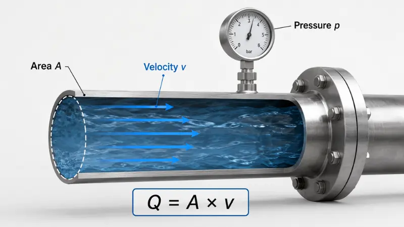
Three terms get blurred together, so it is worth separating them before any formula appears.
- Flow rate is the volume passing a point per unit time, in L/min, m³/h, or GPM. This is usually what you are billed on and what a process actually needs.
- Velocity is the speed of the fluid inside the pipe, in m/s or ft/s. A wide pipe carries a high flow rate at low velocity; a narrow pipe needs a much higher velocity for the same flow rate.
- Pressure is force per unit area, in bar, psi, kPa, or Pa. Differential pressure (the drop between two points) is the quantity that relates to flow; a single static reading does not.
Flow rate and velocity are linked but not interchangeable, and that link is the first formula below.
The Core Flow Rate and Pressure Formulas
There is no single equation that fits every system. The right one depends on the flow regime and which assumptions you can safely make. Here are the six relationships worth knowing.

1. Continuity Equation: Q = A × v
The most basic relationship is Q = A × v, where Q is volumetric flow rate, A is the internal cross-sectional area, and v is average velocity. It does not produce flow from pressure directly, but it explains why diameter dominates everything: area scales with the square of diameter, so a small bore change moves a lot of flow. It is also the equation behind every velocity-based meter, including clamp-on ultrasonic units that measure v and multiply by a known A.
2. Bernoulli's Equation
Bernoulli's equation is an energy balance along a streamline: p + ½ρv² + ρgz = constant. It connects static pressure, velocity, and elevation, and it is the reason static pressure falls where velocity rises through a nozzle, venturi, or diameter change. The catch is in its assumptions - steady, incompressible, frictionless flow. NASA's Glenn Research Center is explicit that the standard form is restricted to inviscid, incompressible, steady flow, which means it is excellent for understanding restrictions and meters but cannot, by itself, account for friction in a long real-world line.
3. Darcy–Weisbach Equation
For most industrial piping, friction governs the pressure drop and flow rate relationship. The Darcy–Weisbach equation estimates that loss:
Δp = f × (L / D) × (ρv² / 2)
It accounts for pipe length, diameter, velocity, density, and a friction factor f that itself depends on the flow regime and pipe roughness. This is the workhorse for "how much pressure will I lose over this run," and it can be inverted to estimate flow from a measured drop when pipe and fluid data are known. As the Engineering ToolBox notes, the equation is valid for fully developed, steady, incompressible flow, and the friction factor is usually pulled from the Colebrook equation or a Moody chart. In practice it is solved iteratively, because f depends on velocity and velocity depends on flow.
4. Hagen–Poiseuille Law
For laminar flow of viscous fluids in small pipes and tubes, use Poiseuille's law:
Q = (π × ΔP × r4) / (8 × μ × L)
The headline term is r4. Flow scales with the fourth power of radius, so internal diameter has an outsized effect - the same point made in the OpenStax treatment of viscosity and laminar flow under Poiseuille's law, where a 5% radius reduction cuts flow by roughly 19%. Note the limit clearly: this applies to laminar flow only, not the turbulent regime most water lines operate in.
5. The Square-Root Law for Differential-Pressure Flow
This is the relationship that most directly answers "can I get flow from pressure," and it is the basis of orifice, venturi, and Pitot measurement:
Q = Cd × A × √(2ΔP / ρ)
The practical takeaway is Q ∝ √ΔP: across a fixed restriction, flow is proportional to the square root of the differential, not to the differential itself. The Engineering ToolBox confirms that in any Bernoulli-based metering device, the flow rate varies with the square root of the pressure difference, with the geometry sized per standards such as ISO 5167 and ASME MFC. It also reminds you that a real discharge coefficient drops the theoretical figure by a few to several tens of percent.
6. Reynolds Number: Laminar vs Turbulent Flow
Before you choose between Poiseuille and Darcy–Weisbach, you need to know the regime. The Reynolds number decides it:
Re = (ρ × v × D) / μ
As a working rule, flow is laminar below about Re 2,000 and turbulent above roughly 4,000, with a transitional band in between - the classification used in the Engineering ToolBox guide to laminar, transitional, and turbulent flow. Clean water in a normal industrial pipe is almost always turbulent; heavy oil in a small tube can be laminar. Pick the formula to match the regime, not the other way around.
A seventh relationship worth a mention for valve sizing is the flow coefficient: Q = Cv × √(ΔP / SG), where Cv (or its metric cousin Kv) captures how much a valve passes for a given pressure drop and specific gravity. Same square-root behaviour, different component.
Which Formula Should You Use?
Use this as a quick selector. The decision usually comes down to flow regime, whether friction matters, and whether you are sizing a meter or a run of pipe.

| Formula | Best for | Key inputs | Main limitation |
|---|---|---|---|
| Q = A × v | Converting a measured velocity to flow; velocity meters | Pipe area, velocity | Needs velocity; gives no pressure information |
| Bernoulli's equation | Understanding restrictions, nozzles, venturis, diameter changes | Pressure, velocity, elevation | Ignores friction; ideal-flow assumptions |
| Darcy–Weisbach | Friction loss in long industrial pipe; estimating flow from a drop | Length, diameter, velocity, density, friction factor | Iterative; needs roughness and a Moody/Colebrook factor |
| Hagen–Poiseuille | Laminar, viscous flow in small pipes and tubes | Pressure difference, radius, viscosity, length | Laminar only; wrong for turbulent water lines |
| Square-root / DP (orifice, venturi) | Measuring flow directly from a differential across a restriction | Differential pressure, area, density, discharge coefficient | Limited turndown; needs a calibrated primary element |
| Valve Cv / Kv | Sizing valves and predicting flow through them | Flow coefficient, pressure drop, specific gravity | Component-specific; not a pipe-run model |
If you are unsure which regime you are in, calculate Re first. Many of the standard methods used to calculate pipeline flow assume turbulent conditions, so applying a laminar formula to a turbulent line is a common source of error.
How to Estimate Flow Rate From Pressure Drop?
When you do want a pressure-based estimate, work the section in order rather than reaching for a single number.

- Step 1 - Measure upstream pressure at a known point with a full pipe.
- Step 2 - Measure downstream pressure across the same defined section.
- Step 3 - Calculate the differential (ΔP = pupstream − pdownstream). This, not the absolute reading, is what relates to flow.
- Step 4 - Confirm internal diameter and length. Use the real bore, not the nominal size, since scale and liners change it.
- Step 5 - Check fluid properties at operating temperature: density and viscosity both shift with temperature.
- Step 6 - Account for friction and fittings. Add equivalent lengths for valves, elbows, and reducers; ignoring them overstates flow.
- Step 7 - Apply the regime-appropriate equation (Darcy–Weisbach for turbulent pipe runs, Poiseuille for laminar tubes, the square-root form for a calibrated restriction) or a vetted calculator.
Engineering note: An estimate is only as good as the measurement points. Take pressure taps where the flow is settled - ideally with several diameters of straight pipe before the tap - and confirm the line is running full. The same discipline applies to flow meters: getting enough upstream and downstream straight pipe is one of the most overlooked install requirements.
Worked Example: From Velocity and Pressure Drop to Flow Rate
Two quick numbers make the behaviour concrete.

Velocity to flow on a DN100 line.
Internal diameter D = 0.1 m, so area A = (π / 4) × D² = 0.7854 × 0.01 = 0.00785 m². With a measured velocity v = 2.0 m/s, flow rate Q = A × v = 0.00785 × 2.0 = 0.0157 m³/s, which is about 56.5 m³/h (roughly 942 L/min). Notice that pressure never entered this calculation - a velocity measurement plus a known bore was enough.
Pressure drop to flow across a fixed restriction.
Because Q ∝ √ΔP, the relationship is far from intuitive. If the differential across an orifice doubles, flow rises only by √2 ≈ 1.41, an increase of about 41% - not 100%. To genuinely double the flow, you would need roughly four times the differential, since 2² = 4. This is exactly why a raw differential signal must have a square-root function applied before it reads as flow, and why small DP errors at low flow translate into large flow errors. It is the kind of detail that explains why two pipes can share the same 3 bar reading yet move very different volumes.
For laminar tubes the r4 term in Poiseuille's law is just as striking: shrink the internal radius by 10% (scale 0.9) and flow falls to 0.94 ≈ 0.66 - a 34% loss from a barely visible change. These conditions, and how the pipe itself shapes the result, are covered well in discussions of the conditions required for an accurate liquid measurement.
Can You Calculate Flow Rate From Pressure Alone?
Usually, no. You cannot calculate flow rate from a single pressure reading, because that one number contains no information about how much energy is being lost between two points. What you need is a differential plus the pipe and fluid context.
Typical required data includes upstream and downstream pressure, internal diameter, length, fluid type, density, viscosity, pipe roughness, and the fittings, valves, bends, and reducers in the path. If a line shows 3 bar at one tap, that is compatible with almost any flow rate: a short wide pipe and a long narrow one can read identically at one point while passing wildly different volumes. The better question is always "what is the pressure drop across this defined section, and what are its pipe and fluid conditions." That framing is what makes a pressure-based estimate realistic, and in critical service it is still verified against an actual meter.
What Changes the Pressure–Flow Relationship?
Several real-world conditions reshape how pressure and flow behave, and most pressure-only surprises trace back to one of them.

Pipe Diameter
Diameter is the strongest lever in the system. A larger bore carries more flow at lower velocity and lower friction loss; a smaller bore forces higher velocity and steeper losses. Because area scales with diameter squared and friction climbs with velocity squared, a modest diameter change has an outsized effect on capacity. This is also why measurement accuracy is so sensitive to the true bore - a theme explored in detail in how pipeline parameters influence measurement accuracy.
Pipe Length
Longer runs accumulate more friction loss. A line that starts at high pressure can arrive at the far end with very little left, so a healthy reading at the pump says nothing about pressure at the point of use.
Fluid Viscosity
Thicker fluids resist movement. Oil, syrup, and many process chemicals need more pressure than water to reach the same flow, and they can push a line from turbulent into laminar behaviour entirely. Viscosity also affects what the meter reports, which is why it is worth understanding how liquid viscosity changes a flow reading before trusting a number on a viscous medium.
Valves and Restrictions
A partly closed valve, a clogged filter, an elbow, or a reducer adds pressure drop and can starve the line of flow even when the pump looks fine. This is the classic high-pressure, low-flow trap.
Elevation
Lifting fluid uphill costs pressure directly through the ρgz term. If pump capacity is limited, flow falls as static lift rises.
Pump Performance
A pump does not deliver the same flow at every pressure. Its curve trades head against flow, so where you sit on that curve - not just the badge rating - sets the operating point.
Common Mistakes When Using Pressure and Flow Formulas
Most pressure-flow errors are variations on a single theme: treating a non-linear, multi-variable system as if one number explained it. The table below pairs the wrong assumption with the better approach.

| Wrong assumption | Better approach |
|---|---|
| High pressure means high flow | Check the differential and the flow regime; a blocked line shows high upstream pressure and almost no flow |
| One gauge reading gives flow | Use a pressure drop across a defined section plus pipe and fluid data |
| Bernoulli works everywhere | Use Bernoulli for restrictions, but add Darcy–Weisbach friction for real pipe runs |
| Diameter is a minor factor | Treat bore as the dominant variable; small changes move large flow |
| Water formulas suit any fluid | Recalculate Re for viscous media and switch to a laminar model when needed |
| Double the differential, double the flow | Remember Q ∝ √ΔP; four times the drop for twice the flow |
When Pressure Readings Are Not Enough: Pairing Sensors With Flow Meters
Pressure sensors and flow meters answer different questions, which is why mature systems run both. A pressure reading tells you whether there is enough driving force and whether the drop across a section looks normal; a flow meter tells you how much liquid is actually moving. A pump can show good discharge pressure while delivering far less than the design flow - only a meter catches that gap.

In practice, a differential pressure transmitter across a primary element gives you the ΔP that the square-root form turns into flow, while a separate flow meter provides an independent check. For a non-invasive verification on a full liquid line, a clamp-on ultrasonic flow meter measures velocity straight through the wall and applies Q = A × v with no process shutdown. On conductive liquids and slurries, electromagnetic flow meters are a common direct-measurement choice, and they are often installed alongside pressure transmitters so operators can see force and flow together.
The medium decides the technology as much as the pressure does. For saturated or superheated steam, vortex flow meters handle the temperature and phase that liquid-oriented methods cannot; for compressed air and process gases, thermal mass flow meters read mass flow directly; and for clean low-viscosity fuels and oils, turbine flow meters remain a precise, cost-effective option. Across water treatment, chemical processing, HVAC, and oil systems, combining pressure and flow data is what turns guesswork into reliable troubleshooting and control.
Frequently Asked Questions
What is the basic formula for flow rate?
The fundamental one is Q = A × v, where Q is flow rate, A is the internal cross-sectional area, and v is average velocity. It converts a measured velocity to flow but does not, on its own, derive flow from pressure.
Can I calculate flow rate from one pressure reading?
Generally no. A single static reading carries no information about energy loss between two points. You need a pressure difference across a defined section plus diameter, length, fluid properties, and friction data.
Does higher pressure always mean higher flow rate?
No. A larger pressure difference can raise flow in a given system, but high static pressure alone does not guarantee it - and because of the square-root relationship, even a real increase in differential yields a smaller proportional rise in flow.
Why is there pressure but no flow?
This usually points to a blockage or a nearly closed valve downstream. Flow stops while upstream pressure builds, so the gauge looks healthy even though nothing is moving. It is the clearest case for adding a flow meter to confirm delivery.
Why does pressure drop when flow increases?
Higher flow means higher velocity and more friction loss along the pipe. Energy dissipated to friction shows up as a falling pressure from inlet to outlet, which is exactly what Darcy–Weisbach quantifies.
Is the flow formula the same for water and oil?
The underlying physics is, but the regime often differs. Water in industrial pipe is typically turbulent, so Darcy–Weisbach applies; viscous oil in a small line can be laminar, where Poiseuille's law is correct. Always recalculate the Reynolds number before choosing.
How much does pipe diameter change the result?
A lot. Capacity scales strongly with bore - area rises with diameter squared, and in laminar flow Poiseuille's r4 term means a 10% radius reduction can cut flow by about a third. Diameter is usually the single most influential variable.
Which formula should I use for industrial pipe flow?
For most turbulent liquid lines, use Darcy–Weisbach for friction and pressure drop; use the square-root differential form when measuring flow through an orifice or venturi; reserve Poiseuille's law for laminar, viscous service. When in doubt, the comparison table above and a Reynolds-number check will point you to the right one. Selecting the matching instrument is a related decision - this guide on how to choose a suitable flow meter is a useful next step.
Can a pressure sensor replace a flow meter?
Only in a calibrated differential-pressure setup, and even then with limited turndown and a known restriction. For a direct, dependable flow value most operators use a meter; for many liquid applications the choice often comes down to ultrasonic versus electromagnetic flow meters, paired with a pressure transmitter for full system visibility.
Key Takeaways
The flow rate and pressure relationship formula is not one rule but a small toolkit. Pressure difference drives flow, yet diameter, friction, viscosity, restrictions, elevation, and pump behaviour all bend the result - and the relationship is non-linear, governed by the square root of pressure drop across any restriction. Do not trust a single pressure reading; work the differential across a known section, match the equation to the flow regime, and confirm with a meter when accuracy matters.
If you are sizing or troubleshooting a liquid pipeline, start by pinning down the medium, the real pipe size, the expected flow range, the pressure conditions, and the installation environment. Get those right and both your calculations and your instruments become far more reliable.


