

A successful industrial flow meter retrofit starts with three questions: Can the meter measure the required flow range, can it be installed safely, and how will its performance be verified?
For suitable liquid pipelines, clamp-on ultrasonic technology can avoid pipe cutting and process interruption. Inline technologies may be better for conductive wastewater, steam, or applications requiring specific measurement capabilities.
This guide focuses on practical retrofit decisions rather than repeating every measurement principle. For a broader technology overview, see the industrial flow measurement selection guide.
1. Assess the Existing Pipeline Before Selecting a Meter
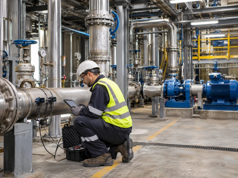
The first step is a site assessment. A flow meter that meets the process specifications may still fail to deliver reliable results at an unsuitable measuring location.
Collect the Operating Data
Record the actual operating conditions, not just the pipeline's original design capacity.
- Fluid: Composition, conductivity, viscosity, solids, gas bubbles, and compatibility requirements.
- Flow range: Minimum continuous, normal, and maximum flow, including reverse flow where applicable.
- Pressure and temperature: Normal values and expected operating extremes.
- Pipe construction: Material, outside diameter, wall thickness, lining, and insulation.
- Measurement purpose: Monitoring, process control, energy management, equipment testing, or commercial accounting.
- Installation restrictions: Shutdown availability, pipe cutting permission, hazardous-area requirements, and maintenance access.
Uncertain flow conditions should be investigated before permanent equipment is purchased. For compatible liquid pipelines, an FT221 portable ultrasonic flow meter may help establish the operating flow range during a temporary survey, subject to its measurement limitations.
Evaluate the Measuring Location
Inspect nearby elbows, valves, pumps, reducers, and branch connections. These can disturb the velocity profile and affect measurement performance.
For ultrasonic measurement, also check whether the pipe remains full, whether the surface is accessible, and whether the pipe wall provides a suitable acoustic path. Thick or poorly bonded linings, heavy deposits, and entrained gas may cause problems.
Siemens' clamp-on flow meter application data sheet demonstrates the level of detail needed for an application review, including fluid properties, pipe dimensions, lining, mounting location, and available straight-pipe length.
Do not automatically apply a fixed 10D upstream and 5D downstream rule to every installation. Follow the selected manufacturer's requirements for the actual upstream disturbance.
Classify the Installation Feasibility
| Site Condition | Recommended Action |
|---|---|
| Full pipe, compatible liquid, accessible mounting section | Proceed with clamp-on suitability and sizing checks. |
| Unknown lining, heavy deposits, or uncertain acoustic conditions | Conduct a field trial before selecting permanent equipment. |
| Partially filled pipe or unsuitable mounting location | Find another location or evaluate a different measurement method. |
| Suitable inline technology with an available shutdown window | Compare installation cost and performance against nonintrusive options. |
2. Choose Between Clamp-On and Inline Flow Measurement
The main retrofit decision is often whether to retain the existing pressure boundary or modify it to install an inline instrument.
Clamp-On Ultrasonic Measurement
A clamp-on ultrasonic flow meter uses external transducers to measure flow without penetrating the pipeline.
It is particularly useful for suitable cooling-water lines, HVAC circuits, and industrial utility water systems where shutdown is difficult.
However, avoiding pipe cutting does not guarantee measurement accuracy. Sensor positioning, pipe dimensions, fluid conditions, and signal quality still determine whether the installation is acceptable.
The clamp-on installation and troubleshooting guide provides additional information about sensor mounting and common measurement problems.
Small-diameter pipes need particular attention because mounting space and acoustic-path geometry become more restrictive. Products such as the FT311 small-pipe ultrasonic flow meter should be evaluated against the actual tube dimensions and minimum operating flow.
Inline Measurement
Inline meters become attractive when process conditions exceed the limitations of external measurement or when the project already includes a scheduled pipe modification.
For conductive water and wastewater, electromagnetic flow meters are important candidates. They require adequate conductivity, appropriate wetted materials, and a properly filled measuring tube.
Process grounding also matters. Emerson's technical note on magnetic flow meter installation and grounding explains how unsuitable grounding arrangements can introduce measurement interference.
For applications where both ultrasonic and magnetic measurement appear practical, compare the technologies against the real fluid and installation constraints using this ultrasonic versus electromagnetic flow meter guide.
Vortex flow meters may be appropriate for steam and certain gas services, provided the minimum operating flow, density, vibration, and steam condition are suitable.
For compatible industrial gases, thermal mass flow meters offer another option, but the calibration gas, composition, and moisture conditions must be checked.
Selection rule: Eliminate technologies that cannot meet the required fluid and accuracy conditions before comparing installation convenience or purchase price.
3. Verify the Flow Range with a Calculation
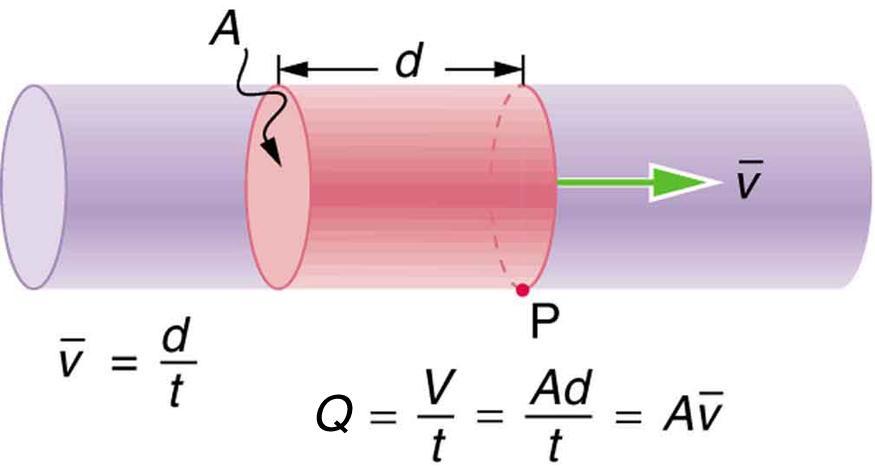
Pipe size alone cannot establish whether an instrument will perform reliably. The actual flow rate must be converted into average velocity and compared with the selected meter's specifications.
Example: An Existing Cooling-Water Pipeline
Consider an illustrative water pipeline with an actual internal diameter of 100 mm:
- Minimum flow: 3 m³/h
- Normal flow: 20 m³/h
- Maximum flow: 40 m³/h
Average velocity is calculated using:
v = Q / A
A = πD² / 4
Where Q is volumetric flow in m³/s, A is internal pipe area in m², and D is the actual internal diameter in meters.
| Operating Point | Flow Rate | Velocity in 100 mm Pipe |
|---|---|---|
| Minimum | 3 m³/h | 0.106 m/s |
| Normal | 20 m³/h | 0.707 m/s |
| Maximum | 40 m³/h | 1.415 m/s |
Compare the Calculation with a Real Meter Specification
FlowT's published FT101 performance data lists a measuring-velocity range beginning at approximately 0.03 m/s. However, the stated ±0.5% of reading accuracy applies from approximately 0.46 m/s upward.
In this example, the normal and maximum velocities fall within that stated accuracy interval, while the minimum velocity does not.
Being inside the measurable range does not mean the meter retains its advertised accuracy at that flow.
Historical FT101 documentation also contains different statements of the lower flow limit. Engineers should therefore obtain the current, configuration-specific specification before making an accuracy commitment.
If the same 3 m³/h passes through a pipe with an actual internal diameter of 200 mm, velocity falls to approximately 0.027 m/s. This is even more demanding and falls below the 0.03 m/s lower measuring-range value stated in the FT101 performance section.
The appropriate next step is to review the required low-flow performance with FlowT, investigate another measuring location, or evaluate a different instrument. Do not assume that changing transmitter settings will restore guaranteed accuracy.
The ultrasonic flow meter range includes different configurations for permanent monitoring and field measurement, but individual performance must be verified rather than transferred between models.
4. Plan the Installation and Compare Retrofit Costs
Once a suitable measurement technology has been identified, the engineering team must establish how it will be installed and commissioned.
For an inline meter, this can involve isolation, draining, pipe modification, welding, pressure testing, and recommissioning.
For clamp-on equipment, the work may involve surface preparation, insulation removal and reinstatement, sensor mounting, cable routing, parameter entry, and signal verification.
Neither approach is installation-free.
Compare Total Installed Cost
Evaluate the equipment purchase price alongside:
- Mechanical and electrical installation
- Production shutdown and restart
- Pressure testing and required permits
- Commissioning and reference verification
- Maintenance access and replacement requirements
- Additional pumping energy caused by permanent pressure loss, where applicable
Suppose an inline instrument has a lower purchase price but requires an unscheduled plant shutdown. The meaningful question is whether that equipment saving exceeds the additional shutdown and construction costs.
If the project already has a planned maintenance window, the cost comparison may change significantly.
Do not assume that clamp-on measurement is always cheaper. Compare complete project quotations under the same measurement and acceptance requirements.
5. Commission and Verify the Installed Flow Meter
A stable reading is useful, but it is not evidence by itself that the installation meets the specified accuracy.
Step 1: Check the Configuration
Confirm pipe dimensions, fluid settings, units, measurement direction, output scaling, and transmitter configuration. For ultrasonic meters, record the available signal-strength and signal-quality diagnostics.
Step 2: Check the Operating Conditions
Verify that the pipe is full, the flow is reasonably stable, and the instrument is operating within its approved range. Record the process conditions during the test.
Step 3: Compare with an Appropriate Reference
Where independent verification is required, use a calibrated reference or a suitably established process measurement method.
For example, if the reference indicates 20.0 m³/h and the installed meter indicates 20.4 m³/h, the relative difference is:
Difference = |20.4 − 20.0| / 20.0 × 100% = 2%
This is a comparison result, not proof that the installed meter has a 2% accuracy error. The reference uncertainty, installation conditions, and flow stability must also be considered.
NIST's water flow calibration documentation illustrates why reference standards and measurement uncertainty are integral to credible flow calibration.
Step 4: Resolve Discrepancies Before Acceptance
If the difference exceeds the agreed tolerance, investigate in a defined order:
- Confirm the reference method and test conditions.
- Recheck the pipe parameters and instrument configuration.
- Review signal diagnostics, installation position, and flow disturbances.
- Check analog or digital output mapping if the discrepancy exists only in the control system.
- Correct the identified problem and repeat the test.
Do not alter a calibration factor simply to match an expected reading without identifying the source of the difference.
For additional background, see the flow meter calibration and verification guide.
6. Two Retrofit Scenarios and Their Engineering Decisions
Scenario A: Cooling-Water Monitoring Without Shutdown
A manufacturing facility needs permanent flow monitoring on a full, continuously operating cooling-water pipeline. The liquid is suitable for transit-time ultrasonic measurement, but production cannot be interrupted.
The initial option is an externally mounted ultrasonic meter. Before ordering, the engineer measures the pipe dimensions, identifies an accessible mounting section, calculates the minimum velocity, and checks the model's accuracy range.
If a field trial produces poor signal quality, the next action is to investigate the measuring location and pipe parameters. Purchasing a permanent transmitter without resolving the acoustic problem would add risk.
Scenario B: Conductive Wastewater During Scheduled Maintenance
A wastewater facility needs permanent flow measurement on a line containing suspended solids. A shutdown is already scheduled, and the liquid has sufficient conductivity.
An electromagnetic meter may be preferable, provided the selected liner, electrodes, flow range, grounding arrangement, and installation conditions are appropriate.
The engineer should confirm the process materials and installation requirements before cutting the line, then establish verification criteria for recommissioning.
These scenarios are illustrative engineering examples, not measured customer projects. They show why installation constraints and measurement performance must be evaluated together.
7. Industrial Flow Meter Retrofit RFQ Checklist
Before asking for a quotation, prepare the following information:
- Fluid, composition, and relevant physical properties
- Minimum, normal, and maximum flow with units
- Operating pressure and temperature range
- Pipe material, actual dimensions, wall thickness, and lining
- Available measuring location and nearby disturbances
- Whether shutdown, pipe cutting, or process penetration is permitted
- Required accuracy and acceptance method
- Power supply, display, 4–20 mA, pulse, or digital communication requirements
- Environmental protection and required approvals
Unknown parameters should be identified rather than estimated without evidence. The supplier can then determine whether a preliminary field survey is required.
Frequently Asked Questions
Can an industrial flow meter be installed without shutting down production?
Yes. Suitable clamp-on ultrasonic meters can be installed externally without cutting the pipe. However, safe access, fluid compatibility, pipe conditions, and measurement performance must be verified.
Is a clamp-on flow meter always the best retrofit option?
No. Inline electromagnetic, vortex, thermal mass, or other technologies may be more suitable for particular fluids and accuracy requirements, especially when planned pipe modification is possible.
What if the available straight pipe length is insufficient?
Check the selected manufacturer's requirements and installation options. A different measuring location, sensor arrangement, or measurement technology may be necessary.
How can I verify that a retrofit meter is accurate?
Compare it with an appropriate reference under representative operating conditions. Consider the uncertainty of both measurements and use acceptance criteria established before commissioning.
Conclusion: Make the Measurement Point Work Before Buying the Meter
An industrial flow meter retrofit should be evaluated as an engineering project, not just an equipment purchase.
Start by understanding the existing pipeline, calculate the real operating flow range, confirm the instrument's limitations, and plan how the installation will be verified.
Need help assessing a flow measurement retrofit?
FlowT can review your pipe dimensions, fluid, operating flow range, installation restrictions, and communication requirements to help identify a suitable measurement approach.
Explore FlowT Industrial Flow Measurement Solutions and share your project specifications for technical evaluation.


