

Choosing the right meter, however, involves more than matching a device to the pipe size. An existing chilled water system may have limited installation space, insulated piping, variable-speed pumps, or a water-glycol mixture that affects measurement conditions. These details can determine whether a meter performs reliably after installation.
For an existing pipeline that cannot be shut down, a clamp-on ultrasonic flow meter is often a practical option. For a new installation with accessible piping, an electromagnetic or inline ultrasonic meter may also be suitable.
This article explains how to compare these technologies, calculate the required measurement range, evaluate installation conditions, and verify performance before accepting a chilled water flow measurement system.
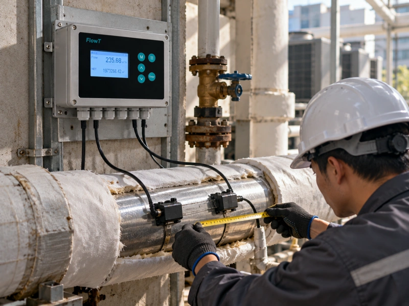
What Is a Chilled Water Flow Meter?
A chilled water flow meter measures the volumetric flow rate of water circulating through an HVAC cooling system. Readings are commonly expressed in cubic meters per hour (m³/h), liters per second (L/s), or gallons per minute (GPM).
In a typical chilled water system, the chiller supplies cooled water to air handling units, fan coils, or heat exchangers. The water absorbs heat from the building or process and returns to the chiller.
Flow measurement helps determine whether each part of the system receives the required water volume. It can also provide operating data for pump control, fault investigation, and energy monitoring.
Where Should Chilled Water Flow Be Measured?
The correct measurement location depends on the information the engineer needs.
- Chiller evaporator connections: Verify flow through individual chillers and investigate operation outside design conditions.
- Main distribution headers: Monitor total circulation flow and system operating trends.
- Building branches: Compare water distribution between different floors or cooling zones.
- Heat exchanger connections: Check whether the equipment receives adequate flow under different cooling loads.
- Temporary testing points: Collect measurements during commissioning, hydraulic balancing, or troubleshooting.
The ASHRAE Handbook chapter on Testing, Adjusting, and Balancing discusses the role of flow measurement in hydronic systems, including chilled water plants, pumping stations, and cooling equipment.
Before selecting a meter, decide whether the objective is temporary testing, continuous monitoring, automatic control, or cooling energy measurement. These applications have different requirements.
Which Flow Meter Is Best for Chilled Water?
Ultrasonic and electromagnetic flow meters are frequently considered for chilled water applications. Mechanical meters may also be appropriate under certain conditions, but their moving components introduce additional maintenance considerations.
Clamp-On Ultrasonic Flow Meters
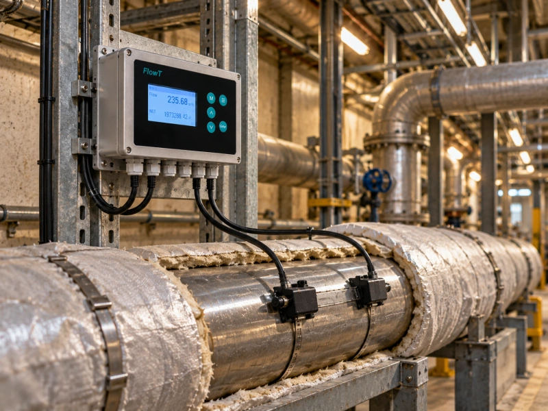
A clamp-on ultrasonic meter measures liquid velocity using transducers installed on the outside of the pipe. In clean chilled water systems, these instruments commonly use the transit-time measurement principle.
The transducers send ultrasonic signals through the pipe wall and liquid. The instrument compares signal travel times in opposite directions and calculates flow using the configured pipe dimensions.
The main advantage is installation without opening the pipeline. Because the transducers remain outside the pipe, they introduce no additional obstruction or pressure loss to the liquid flow.
This makes ultrasonic flow meters particularly attractive for existing commercial buildings, hospitals, data centers, and industrial cooling systems where interrupting water circulation would be difficult.
External measurement still depends on suitable pipe construction and acoustic conditions. Heavy internal scale, unknown lining materials, entrained air, and inaccurate pipe dimensions can reduce measurement reliability.
For retrofit projects, engineers should review the clamp-on ultrasonic flow meter selection requirements before choosing a transmitter or transducer configuration.
Electromagnetic Flow Meters
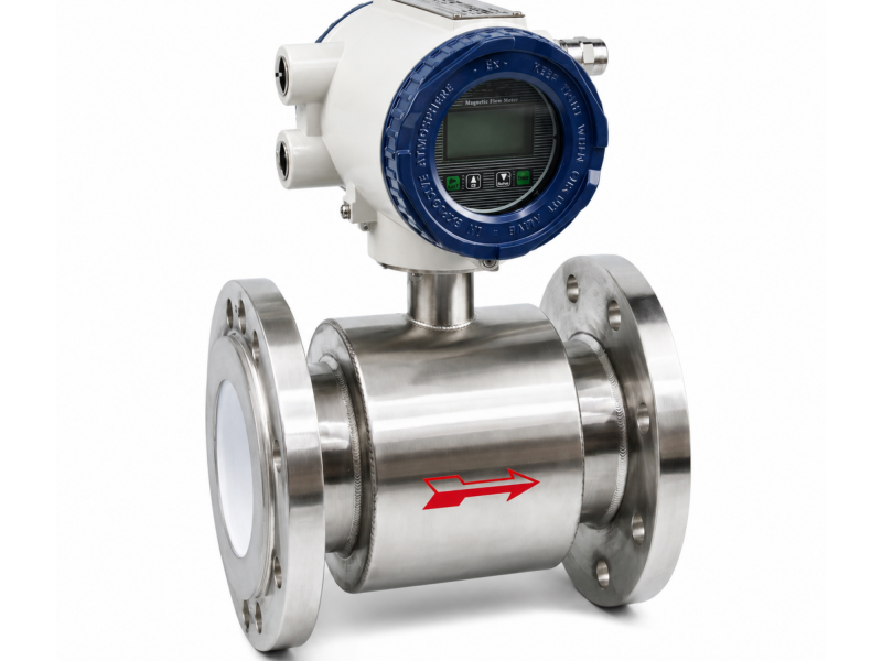
Electromagnetic flow meters use electromagnetic induction to measure conductive liquids. They contain no mechanical rotor and can provide continuous measurement in properly designed piping systems.
An electromagnetic flow meter is often worth evaluating for a new chilled water installation where inline equipment can be incorporated into the pipework during construction.
However, the liquid must meet the selected meter's minimum conductivity requirement. The installation must also satisfy requirements for pipe filling, grounding, electrical connections, and flow profile.
In an existing system, cutting and modifying the pipe may require draining, isolation, welding, pressure testing, and subsequent system restoration.
Portable Ultrasonic Flow Meters
Not every project requires a permanent measurement point.
During HVAC commissioning, an engineer may need to measure several branches over a short period. In this situation, a portable ultrasonic flow meter can be moved between suitable pipe locations.
This approach is useful for comparing pump operation, verifying existing instruments, and investigating uneven water distribution.
Chilled Water Flow Meter Comparison
| Selection Factor | Clamp-On Ultrasonic | Electromagnetic | Portable Ultrasonic |
|---|---|---|---|
| Typical application | Permanent retrofit monitoring | Planned inline installation | Temporary testing |
| Pipe modification | Normally unnecessary | Normally required | Normally unnecessary |
| Liquid conductivity | Not required | Must meet specification | Not required |
| Added flow obstruction | None | None for full-bore designs | None |
| Important limitation | Acoustic path and pipe condition | Conductivity and inline installation | Repeated setup and temporary use |
| Best starting point | Existing operating pipelines | New construction | Commissioning and diagnosis |
These are general selection tendencies, not universal performance rankings. The required accuracy, available flow range, and installation requirements must be checked against the exact model.
For a closer comparison of non-invasive and pipe-mounted configurations, see clamp-on versus inline ultrasonic flow meters.
How to Choose a Chilled Water Flow Meter
A useful selection process starts with the actual operating conditions. The following steps help engineers move from basic system information to a suitable meter configuration.
Step 1: Define the Measurement Objective
Begin by identifying why the measurement is needed.
For commissioning, the instrument may only need to record stable flow values during a series of tests. For continuous monitoring, the meter must operate reliably over changing system loads and provide compatible outputs to the building management system.
For energy accounting, additional requirements may apply to temperature measurement, calibration, data records, and metrological approval.
Do not assume an ordinary process monitoring meter is automatically suitable for regulated or contractual billing.
Step 2: Determine Minimum, Normal, and Maximum Flow
A frequent selection mistake is choosing a meter based only on nominal pipe diameter.
Two pipes of the same size can operate at substantially different velocities. The meter must cover the actual minimum and maximum operating conditions, not just the design flow.
This is especially important in variable-flow HVAC systems. When a variable-speed pump reduces circulation during low cooling demand, the liquid velocity may approach the instrument's minimum usable range.
Before choosing a model, obtain:
- Minimum expected flow during low-load operation
- Normal operating flow
- Maximum design flow
- Expected flow direction and any reverse-flow conditions
- Required accuracy at each operating point
Step 3: Calculate Flow Velocity from Pipe Dimensions
Flow velocity is a useful starting point for checking whether the operating range matches the meter specification.
For a completely filled circular pipe:
Q = A × v
Where Q is volumetric flow rate in m³/s, A is internal pipe cross-sectional area in m², and v is average liquid velocity in m/s.
The internal area is calculated as:
A = π × D² / 4
Here, D represents the actual internal diameter in meters.
For an unlined pipe with uniform wall thickness, the internal diameter can be estimated from the outside diameter minus twice the wall thickness. Internal lining thickness must also be considered where applicable.
The USGS explanation of cross-sectional area and average velocity provides additional background on the relationship between flow and velocity.
Example: Checking a DN100 Chilled Water Pipe
Consider a hypothetical steel pipeline with the following measured or assumed dimensions and operating requirements:
- Outside diameter: 114.3 mm
- Wall thickness: 6.0 mm
- Internal lining: None
- Minimum flow: 3 m³/h
- Normal flow: 18 m³/h
- Maximum flow: 30 m³/h
The estimated internal diameter is:
114.3 − (2 × 6.0) = 102.3 mm
After converting the diameter into meters, the internal cross-sectional area is approximately 0.00822 m².
The corresponding average velocities are:
|
Operating Condition |
Flow Rate | Approximate Velocity |
|---|---|---|
| Minimum load | 3 m³/h | 0.10 m/s |
| Normal operation | 18 m³/h | 0.61 m/s |
| Maximum load | 30 m³/h | 1.01 m/s |
These are illustrative calculations, not field measurements.
The next step is to compare all three velocities with the selected instrument's published measuring range and accuracy conditions.
A meter may detect the minimum flow yet fail to achieve the project's required accuracy at that point. The engineer therefore needs more than a headline maximum-flow specification.
Small pipes and low-flow applications deserve particular attention. FlowT offers an FT311 small-pipe clamp-on ultrasonic solution, but the actual pipe size, flow range, and measurement conditions must be checked before choosing it.
Step 4: Verify Pipe Material and Liquid Composition
For external ultrasonic measurement, the acoustic signal travels through the pipe wall and liquid. Pipe material, wall thickness, internal lining, and surface condition can therefore affect signal transmission.
Steel, stainless steel, copper, and some plastic pipes may be suitable, depending on the selected transducers and configuration. Do not assume that every lined or composite pipe will provide an adequate signal.
The liquid also matters.
Many chilled water systems use water mixed with ethylene glycol or propylene glycol for freeze protection. Glycol changes density, viscosity, sound velocity, and specific heat capacity.
These changes affect how an instrument should be configured and how cooling energy is calculated.
Belimo's technical explanation of glycol-compensated ultrasonic measurement demonstrates why fluid composition matters in HVAC flow applications. Its automatic compensation functionality is specific to the relevant Belimo product designs and should not be assumed for other instruments.
For a FlowT application, provide the glycol type, concentration, operating temperature range, and any relevant fluid treatment information. The manufacturer should verify whether the proposed configuration supports those conditions.
Transit-time measurement generally favors clean, acoustically stable liquids. Where substantial particles or bubbles are present, review the differences between transit-time and Doppler ultrasonic measurement before selecting a technology.
Step 5: Check Installation Space and Pipe Arrangement
The installation location can be as important as the meter specification.
Elbows, partially closed valves, pumps, and reducers may distort the flow profile. The meter might continue displaying a steady reading even when the velocity distribution differs from the conditions assumed during calibration.
For FlowT FT201, the published recommendation is approximately 10 pipe diameters of straight pipe upstream and 5 downstream.
For a DN100 installation, this represents roughly 1 meter upstream and 0.5 meter downstream when using a nominal 100 mm pipe diameter as the planning reference.
These are preliminary planning distances. The actual model instructions and the severity of nearby disturbances determine whether the location is acceptable.
For more on installation constraints, see ultrasonic flow meter piping requirements.
Step 6: Compare Accuracy Requirements Correctly
Accuracy specifications are not always expressed in the same way.
An accuracy of ±1% of reading differs from ±1% of full scale. For example, on a meter with a 100 m³/h full-scale setting, ±1% of full scale corresponds to ±1 m³/h, even when actual flow is much lower.
At a measured flow of 10 m³/h, ±1% of reading corresponds to ±0.1 m³/h. These examples illustrate the definitions; they do not represent guaranteed performance of a particular meter.
Also distinguish accuracy from repeatability. An instrument can produce consistent readings while retaining a systematic measurement error.
For important monitoring points, review the applicable calibration documentation and the uncertainty associated with field installation. FlowT's article on liquid flow meter calibration and traceability provides further background.
Step 7: Confirm BMS Integration
Finally, determine how the measurement will reach the building management system.
Common options include 4–20 mA analog signals, pulse outputs, and RS485 Modbus communication. Availability depends on the selected instrument configuration.
For Modbus installations, confirm the communication settings, register map, data format, measurement units, and totalizer behavior.
For analog outputs, verify scaling. If 4 mA represents zero flow and 20 mA represents a specified maximum, the BMS must use the same range as the transmitter.
A meter that measures correctly but reports incorrectly scaled values can still produce misleading operational trends.
Installation Requirements for Chilled Water Flow Meters
Good installation practice should be treated as part of the measurement system rather than an activity performed after selecting the instrument.
Keep the Pipe Completely Filled
Conventional closed-pipe ultrasonic and electromagnetic meters generally require the measuring section to remain full.
Avoid locations where air can accumulate or where the pipe may partially drain during operation.
For horizontal clamp-on installations, side-mounted transducer positions are often preferred over the very top or bottom of the pipe, subject to the instrument's specified mounting arrangement.
Prepare the Sensor Mounting Surface
External transducers require suitable acoustic contact with the pipe.
Remove loose rust, unsuitable surface coatings, and other material that prevents correct mounting. Enter the verified pipe dimensions and use the coupling medium specified by the manufacturer.
The mounting method, sensor spacing, and alignment must follow the selected instrument's instructions.
For systems where external signal quality cannot be maintained, insertion or pipe-section measurement may be worth evaluating. These alternatives involve different installation requirements, as explained in FlowT's overview of ultrasonic flow meter installation methods.
Protect Against Condensation
Cold pipe surfaces often operate below the surrounding air's dew point. Exposing the pipe during sensor installation may therefore create condensation around the mounting area.
Insulation may need to be opened locally to mount the transducers. After installation, the arrangement should preserve the required acoustic contact, allow future maintenance, and provide suitable vapor sealing and condensation protection.
Check the sensor's environmental protection rating and approved insulation method. A sensor labeled water-resistant is not automatically suitable for every permanently wet or enclosed installation.
How to Verify Flow Meter Performance After Installation
Commissioning should establish more than whether the display shows a flow value.
A practical field verification procedure includes the following checks.
- Verify configuration: Confirm pipe dimensions, liner information, fluid type, sensor spacing, measurement units, and output settings against the recorded installation data.
- Check signal diagnostics: Review signal strength, quality, transit-time diagnostics, or equivalent indicators supported by the instrument. Use the thresholds specified in its manual rather than a universal percentage.
- Observe stable operating conditions: Record flow readings while pump speed, valve positions, and system conditions remain reasonably steady. Investigate unexplained fluctuations.
- Check low-flow operation: Verify that the instrument continues to produce meaningful readings at the minimum expected operating flow, not only at design capacity.
- Verify BMS values: Compare the local display with the values received by the control system. Confirm units, analog scaling, totalizer settings, and communication registers.
- Document the result: Record installation photographs, configuration parameters, diagnostics, operating conditions, and any reference measurements.
If project requirements call for formal accuracy verification, use an appropriate traceable reference method and an agreed acceptance procedure. A simple comparison against a pump curve or another unverified instrument is useful for troubleshooting but does not automatically establish measurement accuracy.
Common Chilled Water Flow Measurement Problems
The displayed flow value is only one part of a measurement diagnosis. Different symptoms can point to different installation or operating issues.
| Observed Problem | Possible Cause | Recommended Check |
|---|---|---|
| Weak ultrasonic signal | Poor coupling, unsuitable lining, corrosion, or incorrect sensor spacing | Inspect the surface, confirm pipe data, and review signal diagnostics |
| Unstable flow reading | Entrained air, disturbed flow profile, or changing operating conditions | Check pipe filling, nearby fittings, and pump operation |
| Reading differs from expectations | Incorrect diameter, inaccurate reference information, or unsuitable meter configuration | Recalculate the internal diameter and compare with reliable reference data |
| Low-flow readings become unreliable | Velocity approaching the instrument's usable lower range | Check minimum-flow specifications and actual operating velocity |
| Local display and BMS disagree | Incorrect output scaling, register mapping, or engineering units | Verify transmitter and control-system configurations |
| Problems appear after insulation work | Sensor movement, damaged cable, or poor mounting contact | Inspect the mounting arrangement and repeat diagnostic checks |
These symptoms are diagnostic starting points, not proof of a particular fault. If an installation repeatedly produces poor acoustic signals, changing to a different mounting position or measurement technology may be more effective than repeatedly adjusting transmitter settings.
Chilled Water Flow Meter Cost: What Should Buyers Compare?
The lowest instrument quotation does not always produce the lowest installed cost.
A fair comparison should include the meter, installation labor, pipe modifications, shutdown requirements, electrical work, commissioning, calibration documentation, and expected maintenance.
For a large existing chilled water header, a clamp-on ultrasonic meter may avoid the cost of draining and modifying the pipe. For a new plant, an electromagnetic meter can sometimes be incorporated into construction with comparatively little additional disruption.
Permanent instruments also require appropriate access, cables, control-system integration, and maintenance planning.
There is no reliable universal price comparison without pipe size, equipment specifications, and project location. Buyers should request quotations based on the same measurement requirements and compare the complete installed scope rather than instrument prices alone.
When Is a BTU Meter Needed Instead?
Flow rate and cooling energy are related, but they are not the same measurement.
A chilled water flow meter measures liquid volume passing through a pipe. A BTU meter combines flow data with supply and return temperature measurements to calculate heating or cooling energy.
For an approximately constant fluid composition, instantaneous cooling power can be estimated from:
Cooling power = Volume flow rate × Density × Specific heat capacity × Temperature difference
The units must be consistent, and suitable fluid properties must be used. Cumulative energy is obtained by integrating thermal power over time.
A high water flow rate does not necessarily mean high cooling output. A small supply-to-return temperature difference can indicate a relatively small heat transfer rate, even when circulation flow is substantial.
For projects requiring energy monitoring, consider a complete ultrasonic flow measurement solution for BTU cooling applications, with the appropriate temperature sensors and calculation capability.
If the result will be used for billing or contractual energy allocation, confirm the complete measurement system's calibration and applicable approval requirements before specifying it.
FlowT Options for Chilled Water Measurement
FlowT supplies ultrasonic flow measurement equipment that can be evaluated for chilled water circulation, HVAC monitoring, and industrial cooling applications.
FT201 Wall-Mounted Ultrasonic Flow Meter
The FlowT FT201 ultrasonic flow meter uses transit-time technology and supports clamp-on or insertion sensor configurations.
Its published specifications include a nominal pipe size coverage of 15–1200 mm, a stated velocity range of approximately ±0.03–5 m/s, and a specified accuracy of ±1% of the measured value under suitable conditions.
Communication and output options include 4–20 mA, pulse outputs, and RS232/RS485 Modbus. Optional RTD temperature sensing configurations can support heating or cooling energy calculations.
These specifications describe the published product capability, not guaranteed accuracy for every installed chilled water system. Sensor selection, fluid conditions, and pipe details must be verified.
FT201 Turbo and Application-Specific Configurations
The FT201 Turbo ultrasonic flow meter is another wall-mounted option with transit-time measurement and available energy-monitoring configurations.
For projects involving difficult pipe access, small-diameter branches, or specialized sensor arrangements, the preferred model should be determined from the actual application rather than from a general product category.
FlowT can review the pipe dimensions, liquid characteristics, flow range, installation environment, and required outputs before recommending a configuration.
Frequently Asked Questions
Can a clamp-on ultrasonic flow meter measure chilled water without shutting down the system?
Yes. External clamp-on transducers can often be installed while a suitable pipeline remains in operation. Safe site access, correct mounting, electrical work, and the instrument's installation requirements must still be addressed.
What is the best flow meter for an existing HVAC chilled water pipe?
A clamp-on ultrasonic meter is often the first option to evaluate when the pipe cannot be cut or drained. However, the final choice depends on pipe material, lining, condition, fluid composition, velocity range, and measurement accuracy requirements.
Does glycol affect ultrasonic chilled water flow measurement?
Yes. Glycol changes several fluid properties. The selected meter must support the actual mixture and operating temperature. Never assume automatic glycol compensation is available unless the manufacturer specifically documents that function.
How much straight pipe does a chilled water flow meter require?
The requirement varies by instrument and nearby disturbances. FlowT FT201 recommends approximately 10D upstream and 5D downstream. Other meter designs may specify different distances. Always use the instructions for the exact model and installation arrangement.
Can a chilled water flow meter measure very low flow?
Some models can, but the minimum measurable velocity and accuracy at that velocity must be checked. Calculate the expected minimum velocity using the actual internal pipe diameter, then compare it with the manufacturer's published measurement limits.
Is a chilled water flow meter the same as a BTU meter?
No. A flow meter measures water flow. A BTU meter uses flow and temperature information to calculate heating or cooling energy. Additional sensors, calculation functions, and calibration requirements may be necessary.
What information is needed before requesting a quotation?
Prepare the pipe outside diameter, wall thickness, material, lining, water or glycol composition, temperature range, minimum and maximum flow, installation photographs, available straight pipe, required accuracy, power supply, and communication interface.
Final Chilled Water Flow Meter Selection Checklist
Before approving the final meter configuration, verify the following:
- Measurement purpose and required data outputs
- Minimum, normal, and maximum operating flow
- Calculated pipe velocity across the operating range
- Actual pipe outside diameter, wall thickness, and lining
- Liquid composition, glycol concentration, and temperature
- Full-pipe conditions and available straight pipe
- Transducer compatibility and installation accessibility
- Accuracy requirements and calibration documentation
- BMS communication and output scaling
- Condensation protection, commissioning, and maintenance access
The best chilled water flow meter is not necessarily the instrument with the widest advertised range or the highest headline accuracy. It is the one that can meet the measurement requirements under the system's actual operating and installation conditions.
For existing HVAC pipelines, clamp-on ultrasonic measurement offers a practical way to obtain flow data without modifying the pipe. For new installations, electromagnetic and inline ultrasonic alternatives should also be evaluated.
Need help selecting a chilled water flow meter?
Send FlowT your pipe details, flow range, fluid composition, installation photographs, and required outputs. Our technical team can review the application, recommend a suitable measurement configuration, and provide the relevant datasheet and quotation.


