

For facility managers and HVAC engineers, this information helps evaluate cooling loads, monitor equipment performance, and track energy consumption across buildings or distribution branches.
However, selecting a BTU meter involves more than choosing an ultrasonic transmitter. Temperature sensor matching, minimum temperature difference, liquid composition, installation conditions, and energy calculation settings all influence measurement reliability.
This article explains how ultrasonic BTU meters work, how to calculate thermal energy, and how to select and verify a complete measurement system.
What Is an Ultrasonic BTU Meter?
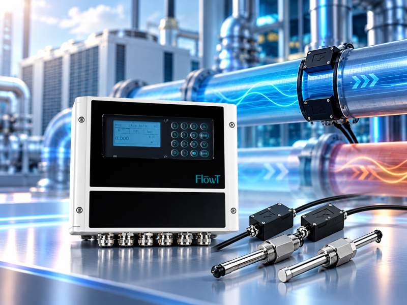
An ultrasonic BTU meter is a thermal energy measurement system that uses ultrasonic technology to determine liquid flow. It also measures the temperature difference between the supply and return pipelines.
BTU stands for British Thermal Unit. HVAC energy meters may display instantaneous thermal power in kW or BTU/h and accumulated energy in kWh, MWh, or BTU.
A standard ultrasonic flow meter measures flow rate and liquid volume. An ultrasonic BTU meter uses additional temperature information to determine how much heating or cooling energy the liquid transfers.
A complete system normally requires three elements:
- Flow sensor: Measures liquid flow through the selected pipeline.
- Temperature sensor pair: Measures supply and return water temperatures.
- Energy calculator: Uses flow, temperature difference, and fluid properties to calculate thermal energy.
These components may be supplied as an integrated assembly or as separate parts. For example, FlowT's ultrasonic energy meter product page describes the FT101 flow meter with optional BTU measurement capability.
The complete configuration, including temperature sensors and calculation functions, must be verified before ordering.
How Does an Ultrasonic BTU Meter Work?
Ultrasonic Flow Measurement
Many ultrasonic BTU meters use transit-time technology. Two transducers transmit ultrasonic signals with and against the liquid flow. The difference in signal travel time is used to calculate flow velocity.
The instrument then determines volumetric flow using the measurement geometry and configured pipe dimensions.
Clamp-on transducers remain outside the pipe, allowing measurement without introducing a mechanical obstruction. However, signal transmission depends on pipe material, wall thickness, liquid condition, and sensor installation.
The basic measurement process is explained further in FlowT's transit-time ultrasonic flow meter information.
Supply and Return Temperature Measurement
Temperature sensors measure the liquid entering and leaving the heat-exchange circuit.
In chilled-water systems, supply water is normally colder than return water because it absorbs heat from the cooling load. In heating systems, supply water is normally warmer because it releases heat to the building.
The difference between these temperatures is called ΔT.
Matched resistance temperature detectors (RTDs), commonly PT100 or PT1000 designs, are frequently used. Their differential measurement performance matters because the energy calculator uses the difference between the two readings.
Energy Calculation
The calculator combines flow with the fluid's thermal properties and measured temperature difference.
It produces two distinct measurements:
- Thermal power: The instantaneous rate of heat transfer, expressed in kW or BTU/h.
- Thermal energy: The accumulated energy transferred over time, expressed in kWh, MWh, or BTU.
Thermal energy is accumulated by integrating power over the operating period. A single instantaneous power reading does not necessarily represent the average load.
How to Calculate BTU Energy in HVAC Systems
For a simplified calculation using approximately constant fluid properties:
Thermal Power (kW) = Flow Rate (m³/h) × Density (kg/m³) × Specific Heat Capacity (kJ/kg·K) × ΔT (K) ÷ 3600
Professional heat meters may use temperature-dependent density and enthalpy values rather than fixed assumptions.
Example: Chilled-Water Cooling Energy
Consider a hypothetical chilled-water system operating under the following conditions:
| Parameter | Assumed Value |
|---|---|
| Flow rate | 20 m³/h |
| Supply temperature | 6°C |
| Return temperature | 12°C |
| Temperature difference | 6°C |
| Water density | 1,000 kg/m³ |
| Specific heat capacity | 4.18 kJ/kg·K |
The estimated cooling power is:
20 × 1,000 × 4.18 × 6 ÷ 3600 = 139.3 kW
This equals approximately 475,000 BTU/h.
If the system maintains these conditions continuously for eight hours, accumulated cooling energy is approximately 1,115 kWh.
This example illustrates the calculation method. It is not a documented project measurement. Actual systems require appropriate fluid properties and time-based energy accumulation.
Why Temperature Difference Matters to BTU Meter Accuracy
A BTU meter's overall energy accuracy cannot be determined from the ultrasonic flow sensor's accuracy alone.
Flow measurement uncertainty, temperature difference measurement uncertainty, fluid properties, and installation conditions all contribute to the final result.
The importance of differential temperature measurement becomes particularly clear in low-ΔT systems.
Small Temperature Differences Increase Relative Error
Suppose the measured temperature difference has a hypothetical systematic error of 0.2°C.
| Actual ΔT | Assumed ΔT Error | Relative ΔT Error |
|---|---|---|
| 6°C | 0.2°C | Approximately 3.3% |
| 2°C | 0.2°C | 10% |
The absolute error is identical, but its relative impact is three times greater when the actual temperature difference falls from 6°C to 2°C.
This example assumes a 0.2°C error in the final differential measurement, not necessarily in either individual temperature sensor. It isolates the temperature difference contribution and does not represent the complete BTU meter uncertainty.
ASHRAE's District Heating and Cooling guidance discusses matched temperature sensors and the importance of measurement accuracy in district energy systems.
How to Evaluate RTD Sensor Performance
For projects with small temperature differences, review the sensor pair's differential accuracy rather than considering individual sensor specifications alone.
Ask the supplier for the matched-pair specification, calibration documentation, allowable temperature difference range, and recommended installation method.
Also consider whether the sensors will be installed in immersion wells or mounted externally. Surface-mounted sensors require suitable thermal contact and insulation, and their performance should be verified for the intended application.
A properly selected flow sensor cannot compensate for an unsuitable temperature measurement arrangement.
Clamp-On vs. Inline Ultrasonic BTU Meters
Both configurations can support thermal energy measurement, but their installation requirements differ.
| Factor | Clamp-On Configuration | Inline Configuration |
|---|---|---|
| Flow measurement | External ultrasonic transducers | Dedicated pipe-section flow sensor |
| Pipe cutting for flow sensor | Normally unnecessary | Required |
| Existing HVAC systems | Useful for suitable retrofits | May require shutdown |
| Measurement geometry | Depends on existing pipe data | Defined by the sensor assembly |
| Temperature sensors | Separate compatible arrangement | Separate or integrated arrangement |
| Typical preference | Non-invasive flow monitoring | Planned permanent installation |
An important distinction is that clamp-on flow measurement does not automatically make the entire BTU system non-invasive. Immersion temperature sensors may still require thermowells or pipe modifications.
For existing installations, review the trade-offs between clamp-on and inline ultrasonic flow meters before finalizing the system arrangement.
How to Choose an Ultrasonic BTU Meter for HVAC
Step 1: Define the Measurement Purpose
Determine whether the system is intended for operational monitoring, performance analysis, internal energy allocation, or commercial billing.
For general monitoring, the main priorities may be stable measurements and BMS compatibility. For billing-related applications, specific calibration, approval, or legal metrology requirements may apply.
The OIML R 75-1 heat meter recommendation describes complete and combined heat meters, including flow sensors, temperature sensor pairs, and calculators.
Compliance with a particular standard must be verified for the complete product and the jurisdiction concerned. A flow meter's published accuracy does not establish billing approval.
Step 2: Check Flow Range and Pipe Conditions
Obtain minimum, normal, and maximum operating flow rates. Variable-speed HVAC pumps can produce low-flow conditions that differ substantially from the design point.
For clamp-on systems, verify actual pipe outside diameter, wall thickness, material, lining, and accessibility.
The expected flow velocities must fall within the instrument's supported measuring range, including the minimum flow where the project requires reliable energy data.
FlowT's clamp-on flow meter selection information discusses the pipe and installation details that should be collected before choosing sensors.
Step 3: Match Temperature Measurement to Minimum ΔT
Identify the lowest temperature difference at which the energy reading must meet the project requirement.
Then review the matched sensor pair's specified performance at that temperature difference.
For example, a project operating regularly near 2°C ΔT requires closer scrutiny of differential measurement uncertainty than one operating consistently at a much larger temperature difference, assuming similar accuracy objectives.
If the available sensor configuration cannot meet the required performance, consider a more suitable temperature sensor arrangement or a different complete energy meter specification.
Step 4: Verify Fluid Compatibility
Water-glycol mixtures require additional attention because glycol changes density, heat capacity, viscosity, and ultrasonic propagation characteristics.
Confirm the glycol type, concentration, and temperature range. Determine whether the calculator supports the actual fluid properties or requires a configured concentration.
Some manufacturers provide model-specific automatic glycol compensation. For example, Belimo's thermal energy meters describe proprietary glycol compensation features. Such functionality should not be assumed for other products.
Step 5: Confirm the Complete Configuration
Before ordering, verify the flow transmitter, ultrasonic sensors, matched RTDs, energy calculation functions, power supply, and communication outputs.
For example, the FlowT FT201 ultrasonic flow meter supports optional RTD-based heating or cooling energy measurement.
Its published ±1% specification applies to flow measurement under suitable conditions. The complete BTU system's energy measurement performance requires separate evaluation.
For BMS integration, request the register map and verify the units and scaling of flow, temperature difference, thermal power, and accumulated energy.
Installation and Commissioning Requirements
Confirm the Measurement Boundary
The flow sensor and both temperature sensors must represent the same thermal energy measurement boundary.
For example, if flow is measured on a building supply connection, the return temperature must represent water leaving that same building circuit. Unaccounted bypasses or mixing connections can make the calculated energy inconsistent with the intended load.
Check Flow Sensor Installation
Select a full-pipe location with suitable straight pipe and minimal flow disturbances. Confirm transducer position, pipe parameters, acoustic coupling, and signal diagnostics.
Installation distances depend on the instrument and surrounding fittings. FlowT's ultrasonic flow meter piping requirements provide related installation guidance.
Install Temperature Sensors Correctly
Supply and return probes should measure representative fluid temperatures. Avoid poor thermal contact, inadequate immersion depth, uninsulated surface probes, and locations where incomplete mixing affects readings.
Cold pipes also require condensation protection. Insulation work should preserve sensor access and follow the approved installation method.
FlowT provides additional information about ultrasonic BTU meter installation.
Verify the System Before Acceptance
- Confirm the flow sensor configuration and signal diagnostics.
- Check supply and return sensor identification.
- Verify temperature readings and ΔT under stable conditions.
- Confirm the correct heating or cooling calculation mode.
- Compare displayed thermal power with an independent calculation using the recorded operating values.
- Verify accumulated energy units and BMS communication.
- Record the installation settings, operating conditions, and calibration documents.
An independent calculation provides a useful reasonableness check, but it does not replace formal calibration or complete-system accuracy verification.
For projects requiring traceable measurement records, consult FlowT's discussion of flow meter calibration and traceability.
Common BTU Meter Problems
| Symptom | Possible Cause | Recommended Check |
|---|---|---|
| Negative cooling power | Reversed temperature inputs or incorrect calculation mode | Verify sensor identification and flow direction |
| Unstable energy reading | Unstable flow or temperature measurement | Check diagnostics and operating conditions |
| Unexpectedly high energy | Incorrect units, sensor offset, or fluid settings | Review calculator configuration |
| Missing BMS energy data | Register, scaling, or communication mismatch | Verify the interface configuratio |
These are diagnostic starting points, not definitive fault diagnoses. Investigate each symptom before replacing instruments or changing calibration settings.
FlowT Ultrasonic BTU Meter Options
FlowT offers ultrasonic flow measurement products with optional thermal energy calculation capabilities for suitable water-based applications.
The FT101-based ultrasonic liquid flow meter with BTU capacity is one option to evaluate where external flow measurement and energy monitoring are required.
FlowT also lists a clamp-on ultrasonic flow meter for BTU cooling-water applications.
These product listings do not establish that every configuration includes the same matched temperature sensors, complete-system accuracy, or billing approvals.
For commissioning or temporary flow verification without a thermal energy calculation requirement, a portable ultrasonic flow meter may be sufficient.
Frequently Asked Questions
Is an ultrasonic BTU meter the same as an ultrasonic flow meter?
No. A flow meter measures liquid flow. A BTU meter combines flow with supply and return temperature measurements to calculate thermal power and accumulated energy.
Can an ultrasonic BTU meter measure both heating and cooling?
Many systems support both modes, but the actual calculator functions and energy totalizers depend on the selected product configuration.
Can a clamp-on BTU meter be installed without shutting down the system?
The external flow sensors can often be installed while the pipeline operates. However, temperature sensor installation may require thermowells or other pipe modifications.
Why does a BTU meter show incorrect energy consumption?
Possible causes include incorrect pipe data, temperature sensor offsets, reversed sensor connections, unsuitable fluid settings, or BMS unit conversion errors.
Can an ultrasonic BTU meter be used for commercial billing?
Only when the complete system meets the applicable regulatory and contractual requirements. General-purpose energy monitoring capability does not automatically establish billing approval.
Final Selection Checklist
Before purchasing an ultrasonic BTU meter, prepare:
- Measurement purpose and required energy units
- Pipe dimensions, material, and installation location
- Minimum, normal, and maximum flow rates
- Supply and return temperature ranges
- Minimum expected temperature difference
- Water or glycol composition
- Required differential temperature accuracy
- Temperature sensor installation requirements
- BMS communication and data recording requirements
- Calibration, verification, and approval requirements
The most suitable ultrasonic BTU meter is the one whose complete flow, temperature, and calculation system meets the actual HVAC measurement requirements.
Clamp-on ultrasonic technology can simplify flow measurement on existing pipelines, but reliable energy monitoring still depends on matched temperature sensors, correct fluid properties, appropriate installation, and verified system performance.
Need help choosing an ultrasonic BTU meter for your HVAC project?
Send FlowT your pipe details, flow range, fluid composition, operating temperatures, minimum ΔT, and required communication outputs. Our technical team can review the application and recommend a suitable configuration.


