VF10 Thermal Gas Mass Flow Meter
The VF10 thermal gas mass flow meter is designed for direct gas mass flow measurement using the thermal conduction principle. Based on constant-temperature-difference technology, it uses two high-grade platinum resistance temperature sensors to detect heat transfer changes caused by flowing gas and convert them into mass flow measurements.
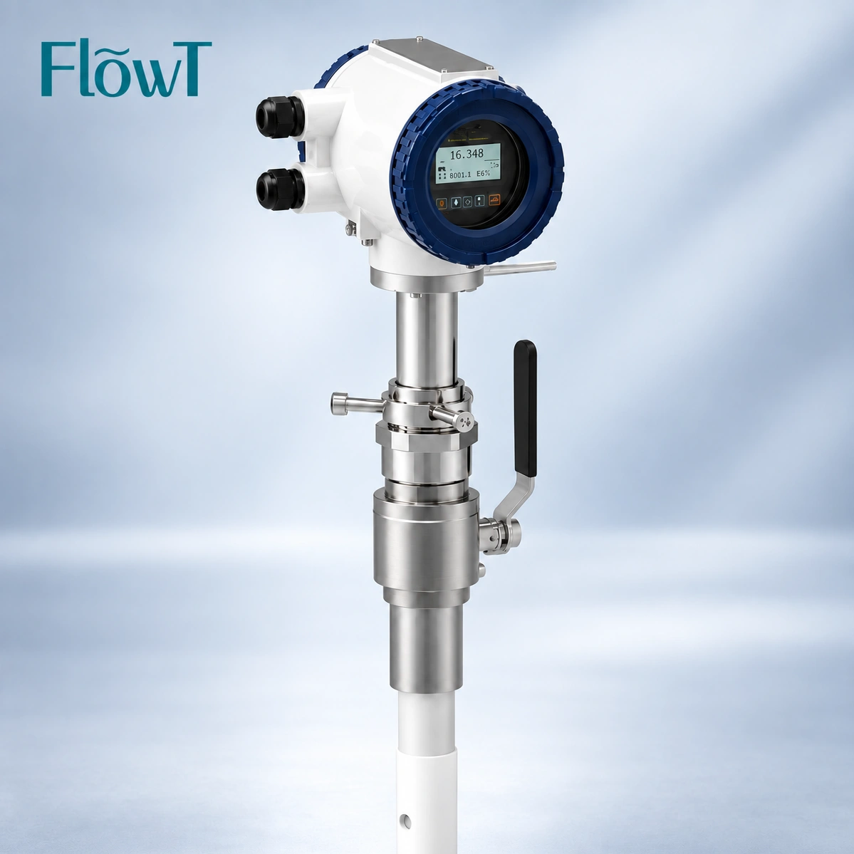
With a wide turndown ratio of up to 100:1, negligible pressure drop, and a compact digital transmitter, VF10 provides a practical solution for industrial gas flow monitoring. Its insertion-type sensor can be installed in circular pipes and rectangular ducts, offering flexibility for different pipeline configurations.
The instrument also supports gas temperature output, cumulative flow calculation, and EEPROM data storage. Each meter is individually calibrated, with calibration arrangements available according to application requirements.
Direct Gas Mass Flow Measurement
Up to 100:1 Turndown Ratio
Flexible Insertion Installation
Why Choose the VF10 Thermal Gas Mass Flow Meter?
Designed for industrial gas measurement, the VF10 combines thermal sensing technology, flexible installation, and digital flow management to support reliable monitoring of gas consumption and distribution.
Key Performance Advantages
Practical features for different gas flow measurement requirements.
Direct Mass Flow Measurement
Measures gas mass flow directly through thermal sensing rather than relying solely on volumetric flow measurement.
Wide Measurement Range
A turndown ratio of up to 100:1 helps accommodate different gas flow conditions within the selected measurement range.
Negligible Pressure Drop
The sensor design produces negligible pressure loss, helping minimize additional resistance in the gas pipeline.
Flexible Installation
The insertion-type design supports installation in circular pipelines and rectangular ducts for different industrial layouts.
How Does the VF10 Thermal Mass Flow Meter Work?
Constant Temperature Difference Measurement Principle
The VF10 operates according to the thermal conduction principle. Its sensing assembly contains two platinum resistance temperature sensors connected through a bridge-type circuit.
One sensor measures the actual gas temperature and provides a reference. The other sensor is heated and maintained at a constant temperature difference above the gas temperature.
When gas passes the heated sensor, it carries away heat through convection. The amount of heat transferred changes with gas flow. The electrical power required to maintain the preset temperature difference is then used by the measuring system to determine gas mass flow.
Dual platinum RTD sensors
Constant temperature difference control
Thermal energy transfer detection
Step 1: Temperature Reference
The first platinum RTD sensor measures the actual gas temperature.
Step 2: Sensor Heating
The second sensor maintains a controlled temperature difference above the gas temperature.
Step 3: Heat Transfer
Flowing gas removes heat from the heated sensor, changing the energy required to maintain the temperature difference.
Step 4: Flow Calculation
The measuring electronics convert the thermal response into gas mass flow information.
Because thermal mass flow measurement depends on heat transfer properties, gas composition and calibration conditions should be considered when selecting the instrument. If the gas composition changes significantly during operation, consult the manufacturer about the appropriate calibration arrangement.
VF10 Transmitter and Sensor Features
Digital Transmitter Design
The VF10 transmitter adopts a modular design to improve measurement efficiency and simplify operation. Its user-friendly parameter menu allows operators to configure measurement settings and access flow information more conveniently.
| Modular Design | A modular instrument structure supports efficient measurement operation. |
| Parameter Configuration | A convenient operating menu allows users to set instrument parameters. |
| Flexible Display | Measurement information can be displayed through the transmitter interface. |
| Flow Totalization | The instrument can cumulatively calculate gas flow for consumption monitoring. |
| EEPROM Memory | Stored information is retained during a power outage, according to the original VF10 product specifications. |
Platinum RTD Sensor Design
The VF10 sensor assembly uses two benchmark-grade platinum resistance temperature sensors. Their coordinated operation enables the instrument to monitor gas temperature and thermal response simultaneously.
- One platinum RTD sensor measures the gas temperature.
- The second platinum RTD sensor maintains a constant temperature difference above the gas temperature.
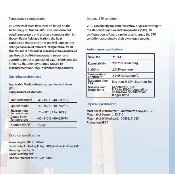
- The sensor is designed for gas flow measurement under high-temperature and high-pressure conditions, subject to the specified operating limits.
- The sensor generates negligible pressure loss under suitable installation conditions.
- Each instrument is individually calibrated according to the selected calibration requirements.
VF10 Thermal Gas Mass Flow Meter Specifications
Key technical characteristics of the VF10 thermal gas mass flow meter are summarized below.
| Product Model | VF10 |
| Product Type | Thermal Gas Mass Flow Meter |
| Measurement Principle | Thermal Conduction / Constant Temperature Difference |
| Measured Medium | Gas |
| Primary Measurement | Gas Mass Flow |
| Additional Measurement | Gas Temperature Output |
| Sensor Elements | Two Platinum Resistance Temperature Sensors (RTDs) |
| Turndown Ratio | Up to 100:1 |
| Pressure Drop | Negligible |
| Installation Type | Insertion Type |
| Applicable Pipe Shape | Circular Pipes and Rectangular Ducts |
| Transmitter Design | Modular Design |
| Flow Totalization | Supported |
| Data Storage | EEPROM Memory |
| Calibration | Individual Calibration; Calibration Scheme Available According to User Requirements |
| Optional Accessory | Ball Valve Accessories for Applicable Low-Pressure, Non-Toxic Gas Installations |
Thermal Gas Mass Flow Meter Applications
Thermal mass flow measurement is commonly used in industrial gas monitoring, consumption management, and process control. The following are potential application directions for VF10, subject to gas compatibility, calibration, and process-condition confirmation.
Industrial Gas Measurement Applications
Flexible gas measurement solutions for different industrial operating environments.
Compressed Air Systems
Monitor compressed air consumption across production lines, distribution pipelines, and industrial utility systems to support energy management and leakage investigations.
Natural Gas Distribution
Measure gas consumption in industrial supply pipelines and distribution networks where the selected gas calibration and process limits are suitable.
Boiler and Burner Systems
Monitor fuel gas flow in industrial heating systems to provide measurement data for operational monitoring and combustion management.
Industrial Gas Distribution
Track gas consumption across different production areas, process equipment, and plant utility pipelines.
Air Duct Measurement
The insertion configuration can be considered for suitable circular pipelines and rectangular air ducts used in industrial ventilation systems.
Wastewater and Biogas Systems
Potential applications include biogas and aeration-related gas monitoring, subject to moisture, contamination, material compatibility, and calibration requirements.
For gas applications involving variable mixtures, moisture, particles, corrosive components, or potentially explosive atmospheres, the gas composition and site safety requirements should be evaluated before ordering.
How to Select and Install a VF10 Thermal Mass Flow Meter
Correct selection and installation are important for obtaining representative gas flow measurements. Before ordering the VF10, prepare the following application information for technical evaluation.
Installation Information Checklist
| Information Required | Details to Provide |
| Gas Type | Gas name and composition |
| Flow Range | Minimum, normal, and maximum flow rates |
| Pipeline | Diameter or width, height, and wall thickness |
| Process Conditions | Operating temperature and pressure |
| Installation | Pipe layout, available straight runs, and mounting position |
| Instrument Configuration | Required display, outputs, accessories, and calibration |
Calibration and Maintenance Considerations
Thermal mass flow measurement relies on the relationship between gas flow and heat transfer. Correct calibration and appropriate sensor maintenance help maintain measurement consistency over the instrument's service life.
Individual Calibration
Each VF10 instrument is individually calibrated. Calibration arrangements can be determined according to the user's measurement requirements.
Gas Compatibility
The actual gas type and composition should be considered during calibration. Significant changes in gas composition may require technical reassessment.
Sensor Inspection
Check for moisture, deposits, corrosion, or other contamination that could affect heat transfer. Inspection and cleaning should follow the manufacturer's instructions.
For applications involving wet gas, dust, condensate, or corrosive components, discuss the required sensor material and protection arrangements before installation. Maintenance frequency should be determined by actual process conditions and operating experience.
Frequently Asked Questions About VF10
01. What is the measurement principle of the VF10 thermal mass flow meter?
The VF10 uses the thermal conduction principle and constant-temperature-difference technology. Two platinum resistance temperature sensors detect gas temperature and the heat transfer response, allowing the transmitter to calculate gas mass flow.
02. Can the VF10 measure gas temperature as well as mass flow?
Yes. According to the product specifications, gas temperature can also be output by the measuring system in addition to gas mass flow measurement.
03. What is the turndown ratio of the VF10?
The VF10 has a turndown ratio of up to 100:1. The appropriate operating range should be confirmed according to the actual gas flow conditions and calibration requirements.
04. Does the VF10 thermal mass flow meter cause pressure loss?
The product specification describes the pressure drop or pressure loss as negligible. The actual installation should still be evaluated according to pipeline conditions and sensor configuration.
05. Can the VF10 insertion sensor be installed in rectangular ducts?
Yes. The original product information specifies that the insertion-type instrument can be installed in circular or rectangular pipes. The installation dimensions and insertion position should be confirmed before ordering.
06. Can the VF10 sensor be removed without dismantling the pipeline?
Ball valve accessories are available for applicable insertion-type installations, allowing easier sensor removal or replacement in low-pressure, non-toxic gas environments. Confirm the specific pressure conditions and safety procedures with the manufacturer before attempting removal.
07. Is the VF10 suitable for different gas types?
Gas compatibility and calibration must be evaluated for the actual medium. Provide the gas name, composition, operating pressure, temperature, and flow range so the manufacturer can confirm suitability.
08. Is every VF10 thermal gas mass flow meter individually calibrated?
Yes. Each instrument is individually calibrated, and the calibration scheme can be determined according to the user's application and measurement requirements.
Explore More Flow Measurement Solutions
Explore other FlowT flow measurement products and technical resources to identify a suitable solution for your industrial measurement requirements.
Thermal Mass Flow Meter
Explore FlowT's thermal mass flow measurement product range for industrial gas applications.
Mass Air Flow Meter
Learn more about mass air flow measurement solutions and related product configurations.
Air Mass Flow Meter
Explore air mass flow measurement options for industrial applications.
Thermal Mass Flow Meter Solutions
Discover another thermal mass flow meter product configuration from FlowT.
For more information about instrument configuration and signal processing, you can also read our guide to what a flow transmitter is and how it works.
Looking for a Reliable VF10 Thermal Gas Mass Flow Meter?
Tell us your gas type, pipeline dimensions, operating flow range, temperature, and pressure. Our team can help evaluate the VF10 configuration, calibration requirements, and suitable installation arrangement for your application.
Hot Tags: thermal gas mass flow meter, VF10 thermal mass flow meter, thermal flow meter supplier, gas mass flow meter, insertion thermal mass flow meter, air flow measurement in energy savings initiatives, flow measurement in building automation systems, mass flow measurement in cement manufacturing operations, gas flow measurement in kiln operation, flow meter for mining industry, mass flow meter for environmental protection