

The principle sounds simple, but reliable orifice flow measurement depends on more than the plate itself. Bore diameter, beta ratio, edge condition, pressure tap location, fluid density, Reynolds number, upstream flow profile, DP transmitter range and installation all influence the result.
This guide explains the orifice flow meter working principle from the hydraulic restriction to the final flow signal, then shows what affects measurement uncertainty, where the technology works well and what engineers should check before specifying a system.
What Makes Up an Orifice Flow Meter?
An orifice meter should be treated as a complete differential-pressure measurement system rather than as a metal plate installed between two flanges.
Orifice Plate
The plate creates the restriction. A conventional concentric sharp-edged plate has a circular bore centered in the pipe. Its bore size, thickness, upstream edge and installation orientation must match the design basis used for the flow calculation.
Different plate geometries are available for particular services. The guide to choosing an orifice plate type provides additional context when a standard concentric plate may not suit the fluid.
Pressure Taps and Impulse Connections
Pressure taps sense static pressure on the upstream and downstream sides of the restriction. Tubing or integrated passages carry these pressure signals to the differential pressure instrument.
The tapping arrangement is part of the measurement design. It cannot be moved arbitrarily after the plate has been sized because pressure varies with position around the restriction.
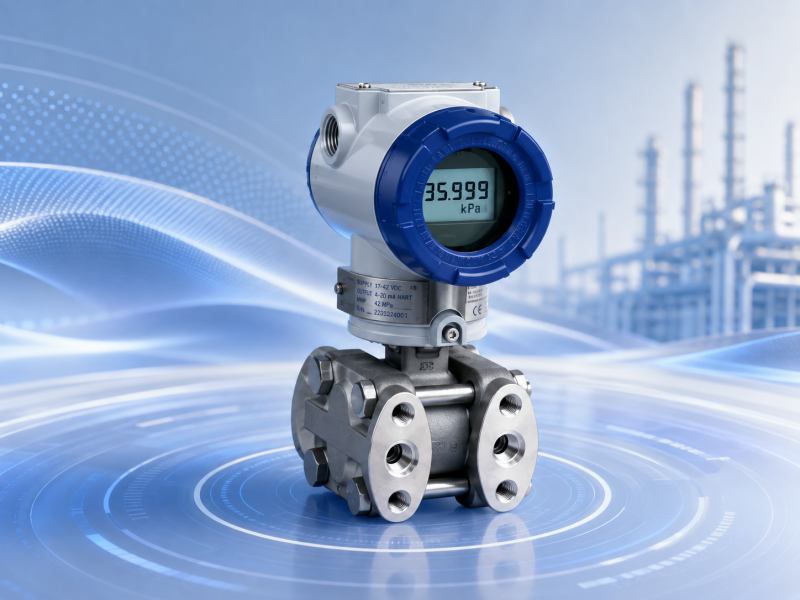
Differential Pressure Transmitter
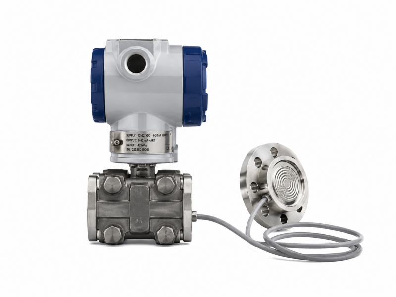
The secondary measurement element detects the difference between the high-pressure and low-pressure sides. A suitable differential pressure transmitter converts that mechanical pressure difference into a usable electronic signal.
More broadly, pressure transmitter configurations should be selected according to process pressure, temperature, required span, environmental conditions and control-system requirements.
How Does an Orifice Flow Meter Work?
1. Fluid Approaches the Restriction
Upstream of the plate, the fluid occupies the full pipe cross-section. For standardized measurement, the approaching flow should meet the installation conditions required by the chosen calculation method. Nearby elbows, valves and other disturbances can change the velocity profile before the fluid reaches the orifice.
2. Velocity Increases Through the Orifice
The bore provides less flow area than the pipe. To maintain continuity, the fluid accelerates as it passes through the opening.
This acceleration is central to differential-pressure flow measurement. The meter does not directly measure velocity at the plate; instead, it measures the pressure change associated with the acceleration.
3. Static Pressure Falls
As velocity rises, static pressure decreases. Bernoulli's principle provides the basic physical relationship between pressure, velocity and elevation for an idealized flow, while practical orifice calculations add coefficients that account for real fluid behavior.
The upstream pressure is therefore higher than the pressure measured on the downstream side of the restriction.
4. A Vena Contracta Forms Downstream
The fluid stream does not immediately expand to the full pipe diameter after crossing the plate. It continues to contract for a short distance downstream. The location where the jet reaches its minimum cross-sectional area is called the vena contracta.
After this point, the stream expands and some static pressure is recovered. Recovery is not complete because separation and turbulence dissipate mechanical energy. This unrecovered portion appears as permanent pressure loss.
5. The System Measures Differential Pressure
The transmitter sees two pressure signals:
ΔP = P1 − P2
where P1 is the upstream tapping pressure and P2 is the downstream tapping pressure.
As flow increases, differential pressure rises. The relationship, however, is nonlinear.
6. Differential Pressure Is Converted Into Flow
For a fixed geometry and otherwise stable process conditions, the simplified relationship is:
Q ∝ √ΔP
This has an important practical consequence. If differential pressure falls to 25% of its full-scale value, the corresponding theoretical flow is about 50% of full scale, not 25%.
The square-root function may be performed inside a smart transmitter or in a PLC, DCS or flow computer. It should not normally be applied twice. Emerson's DP flow engineering guide specifically notes that square-root extraction can be performed in the transmitter or elsewhere in the control system and warns against performing it in both locations.
The resulting signal may also be accumulated by a flow totalizer when the application requires total volume or mass over time.
What Goes Into the Actual Orifice Flow Equation?
The square-root relationship explains the principle but is not a complete engineering sizing equation. Actual calculations account for the geometry and behavior of the primary element and the properties of the fluid.
Important variables include:
- orifice bore diameter;
- pipe inside diameter;
- differential pressure;
- fluid density;
- discharge coefficient;
- beta ratio;
- Reynolds number;
- expansibility factor for compressible fluids.
Discharge Coefficient
The discharge coefficient, commonly represented by C, accounts for the difference between an idealized flow calculation and actual flow through the restriction. It is influenced by the geometry and flow regime, which is why a standard orifice plate cannot be replaced with an approximately similar hole and expected to produce the same calculation basis.
Plate edge condition also matters. Rounding, deposits, erosion or mechanical damage can change the local flow behavior and therefore affect measurement performance.
Expansibility Factor
For liquids, density changes through the differential pressure element are often small enough to treat the fluid as essentially incompressible for the applicable calculation. Gas and steam behave differently.
As a compressible fluid passes through the restriction, pressure changes are accompanied by density changes. The expansibility factor accounts for this effect in the applicable orifice calculation. This is one reason gas and steam sizing requires more process information than simply pipe diameter and maximum flow.
What Is Beta Ratio and Why Does It Matter?
Beta ratio, written as β, is the ratio between the orifice bore diameter and the pipe inside diameter:
β = d / D
where d is the orifice bore diameter and D is the upstream pipe inside diameter.
A smaller bore relative to the pipe creates a stronger restriction and generally produces more differential pressure at a given flow. A larger bore produces less differential pressure and usually less permanent pressure loss.
That does not mean either a very small or very large beta ratio is automatically better. Beta ratio interacts with Reynolds number, discharge coefficient, available DP, uncertainty and installation sensitivity. It should be calculated from actual process conditions rather than chosen only to create a convenient transmitter span.
Which Pressure Tap Arrangement Is Used?
ISO 5167-2:2022 covers standard orifice plates used with flange taps, corner taps, and D and D/2 taps. The official ISO 5167-2 specification also defines geometry, installation and operating conditions for standard plates used in full circular conduits.
Flange Taps
Pressure connections are located in the flanges at standardized distances near the plate. This is a common industrial arrangement.
Corner Taps
The pressure is sensed immediately adjacent to the upstream and downstream faces of the plate.
D and D/2 Taps
The upstream tap is positioned one pipe diameter upstream, while the downstream tap is located at half a pipe diameter downstream.
These arrangements do not simply provide three different ways to connect tubing. Tap location changes the differential pressure being measured, so the tapping configuration must match the calculation method used to determine flow.
What Affects Orifice Flow Meter Accuracy and Measurement Uncertainty?
It is more useful to think about the uncertainty of the complete measurement system than to assign one generic accuracy number to every orifice meter.
Primary Element Geometry
Bore diameter, plate flatness, thickness, sharp-edge condition and pipe diameter all influence the primary measurement. A plate manufactured correctly but installed backward can also produce a result outside the intended design basis.
Flow Profile
Elbows, partially open valves, reducers and other fittings can create swirl or asymmetric velocity profiles. The effect depends on the disturbance, its distance from the plate and the meter geometry.
This is why there is no useful universal statement that every orifice meter needs exactly the same number of pipe diameters upstream. Standard installation requirements should be checked for the actual piping configuration.
Reynolds Number
Reynolds number describes the relationship between inertial and viscous effects in the flowing fluid. Because the discharge coefficient is related to flow regime, Reynolds number forms part of the standardized calculation and applicability limits.
ISO 5167-2 specifies defined operating conditions and application limits rather than treating the plate coefficient as independent of the flow regime.
DP Transmitter Span
A transmitter that performs well near its designed operating range may contribute proportionally more uncertainty when the differential pressure becomes very small.
This matters because DP drops rapidly as flow decreases. If flow is 30% of design flow, differential pressure is only about 9% of the corresponding design DP under the simplified square relationship.
Low-flow performance therefore depends on more than the nominal transmitter accuracy printed on a datasheet.
Pressure Taps and Impulse Lines
Blocked taps, leaks, unequal liquid heads, trapped gas or condensate can produce a false differential pressure before the transmitter even processes the signal.
This is why checking the complete pressure path is often more useful than immediately recalibrating the transmitter when a reading becomes unstable.
Fluid Density and Compensation
For changing gas or steam conditions, density may vary enough to affect calculated flow. A multivariable system can incorporate static pressure and temperature so the calculation reflects changing process conditions.
Calibration remains part of the overall measurement-management process. The site's guide on how to calibrate a flow meter provides further background, while pressure instrumentation may need its own documented pressure transmitter calibration interval.
Where Are Orifice Flow Meters Used?
Liquid Flow
Orifice plates can measure many clean, single-phase liquids when pressure loss and installation conditions are acceptable. Water, process liquids and hydrocarbons are common examples.
Dirty liquids require more caution. Deposits may change the bore geometry, while solids can erode the edge or obstruct pressure taps.
Gas Flow
Differential-pressure measurement is also widely used for gas. Compressibility and density variation, however, must be considered. A system intended to report standard volume or mass flow may need pressure and temperature compensation in addition to DP.
Readers evaluating gas applications can continue with the site's industrial gas flow measurement resources.
Steam Flow
Steam is an important DP-flow application because the primary element has no rotating measurement mechanism exposed to the high-temperature process.
The difficult part is often not the plate but the pressure measurement system. In conventional wet-leg arrangements, condensate in the impulse lines should be managed so both sides present a stable and comparable pressure head to the transmitter. Poor line slope, unequal condensate legs or steam entering the transmitter can create measurement and reliability problems.
Steam density also changes with operating condition, so a system used across a broad pressure or temperature range may require compensation. Alternative steam technologies are discussed in the site's steam flow meter section.
When Is an Orifice Plate a Poor Choice?
An orifice system is attractive because the primary element is simple and standardized, but its trade-offs matter.
- High permanent pressure-loss cost: if pump or compressor energy is critical, another primary element may provide better pressure recovery.
- Abrasive or deposit-forming fluid: edge erosion and blocked taps can undermine the measurement.
- Very wide operating range: low flow produces very small DP, which can make the complete system less suitable than another technology.
- Strong pulsation: standard ISO 5167-2 scope excludes pulsating flow.
- Poor upstream piping: severe swirl or velocity-profile distortion may make a standard installation impractical without redesign.
- Direct mass flow required: an orifice system generally requires additional pressure, temperature and density information rather than inherently measuring mass.
Orifice vs Venturi, Vortex, Turbine and Coriolis
| Technology | Main Strength | Main Consideration |
|---|---|---|
| Orifice | Standardized, simple primary element | Higher permanent pressure loss and installation dependence |
| Venturi | Better pressure recovery | Larger and usually higher initial equipment cost |
| Vortex | Useful for many steam, gas and liquid services | Needs suitable Reynolds number and flow conditions |
| Turbine | Responsive measurement for clean, free-flowing fluids | Contains a rotating measurement element |
| Coriolis | Direct mass flow and density measurement | Different cost, pressure-drop and installation considerations |
A Venturi flow meter is particularly worth comparing when permanent pressure loss is important. The gradual converging and recovery sections normally retain more pressure than the abrupt expansion downstream of an orifice.
For steam or utility service, compare the application with a vortex flow meter. For clean liquids where a mechanical rotor is acceptable, the turbine flow meter range provides another measurement approach. Where direct mass flow is the priority, the site's guide to the Coriolis flow meter working principle explains a fundamentally different method.
Conductive liquid services may also justify comparison with an electromagnetic flow meter, particularly when eliminating an intrusive restriction is desirable.
How to Select an Orifice Flow Meter
A useful specification begins with the process, not with the flange size.
- Identify the fluid and phase. State whether the process is liquid, gas or steam and whether it remains single phase under operating conditions.
- Provide minimum, normal and maximum flow. A single design flow is not enough to evaluate low-flow DP or required rangeability.
- Define pressure and temperature. Include normal and design conditions. Gas and steam calculations may also need these values for density compensation.
- Confirm pipe inside diameter. Nominal pipe size is not always sufficient for an accurate primary-element calculation.
- Determine allowable permanent pressure loss. This may become a lifecycle-energy constraint rather than merely an instrumentation issue.
- Select plate geometry and material. Consider fluid cleanliness, corrosion, temperature and applicable standards.
- Establish beta ratio and design DP. These should be calculated together rather than independently selected.
- Choose the required tap arrangement. The taps must match the calculation basis.
- Size the DP transmitter. Evaluate the expected DP across the real operating range, not only at maximum flow.
- Define compensation and output. Determine whether the system needs square-root extraction, totalization, pressure/temperature compensation or mass-flow calculation.
- Check the piping layout. Review upstream disturbances, straight-run requirements, transmitter location and impulse-line routing before finalizing the design.
Common Installation and Commissioning Errors
| Problem | Why It Matters | What to Check |
|---|---|---|
| Plate installed in the wrong direction | Changes the intended sharp-edge geometry | Plate markings, bevel direction and drawing |
| Incorrect pipe ID entered in sizing | Changes beta ratio and calculated flow | Actual pipe schedule and internal diameter |
| Valve or elbow too close upstream | Can distort the approaching velocity profile | Applicable straight-run requirement |
| Plugged pressure tap | Creates false or slow DP response | Taps, manifolds and impulse lines |
| Gas trapped in liquid impulse line | Changes the transmitted pressure head | Line routing and venting |
| Unequal condensate legs in steam service | Introduces a differential head unrelated to flow | Condensate level and impulse-line arrangement |
| Square root applied twice | Creates a major flow calculation error | Transmitter and DCS configuration |
| Transmitter span too wide | Weakens useful low-DP measurement performance | Actual min/max DP and required turndown |
Emerson describes DP flow systems as a combination of the primary element, differential pressure transmitter and supporting components such as impulse piping, valves and connectors. That system-level view is useful during troubleshooting because a good plate cannot correct a bad pressure signal. See Emerson's differential pressure flow measurement overview for additional technical background.
Frequently Asked Questions
Is an orifice flow meter a differential pressure flow meter?
Yes. The orifice plate creates a controlled pressure difference, and the measurement system uses that DP to determine flow.
Why does flow vary with the square root of differential pressure?
For fixed geometry and stable fluid conditions, differential pressure varies approximately with the square of flow. The calculated flow therefore varies with the square root of DP.
What is the main disadvantage of an orifice meter?
Permanent pressure loss is one of the main trade-offs. The abrupt restriction and downstream flow separation dissipate energy that is not fully recovered.
What is beta ratio?
Beta ratio is the orifice bore diameter divided by the pipe inside diameter. It affects generated DP, discharge behavior, pressure loss and the applicable sizing conditions.
Can an orifice flow meter measure steam?
Yes. The primary element is well suited to high-temperature service, but accurate steam measurement also depends on steam condition, density calculation, pressure and temperature information, and correct impulse-line installation.
Does every orifice plate require the same straight pipe length?
No. The requirement depends on the upstream disturbance, beta ratio, piping arrangement and applicable calculation standard. A single straight-run number should not be applied to every installation.
How often should an orifice flow meter be calibrated?
There is no universal interval for the complete system. Calibration frequency should reflect measurement criticality, transmitter stability, service conditions, maintenance history and quality-system requirements. Plate inspection and pressure-path checks are separate from transmitter calibration.
Can ISO 5167 be used for every orifice application?
No. ISO 5167-2 defines a specific scope for standardized orifice plates and operating conditions. According to the official standard summary, it applies to full conduits, specified pressure-tapping arrangements, single-phase subsonic flow and defined size and Reynolds-number ranges; pulsating flow is outside its stated scope.
Conclusion
An orifice flow meter converts a controlled hydraulic restriction into a differential pressure that can be related to flow. The plate creates the velocity and pressure change, pressure taps transmit the resulting signals, and the DP transmitter or control system performs the conversion needed for flow indication and totalization.
Reliable measurement depends on the complete system. Beta ratio, discharge coefficient, Reynolds number, fluid density, plate condition, flow profile, pressure tap arrangement, transmitter span and compensation all influence the final result.
For a new application, define the fluid, phase, operating flow range, pressure, temperature, pipe ID, allowable pressure loss and required measurement performance before sizing the plate. Then verify that the piping arrangement and transmitter can support the expected DP range. That process makes it much easier to determine whether an orifice meter is appropriate or whether Venturi, vortex, turbine, electromagnetic or Coriolis technology offers a better fit.


