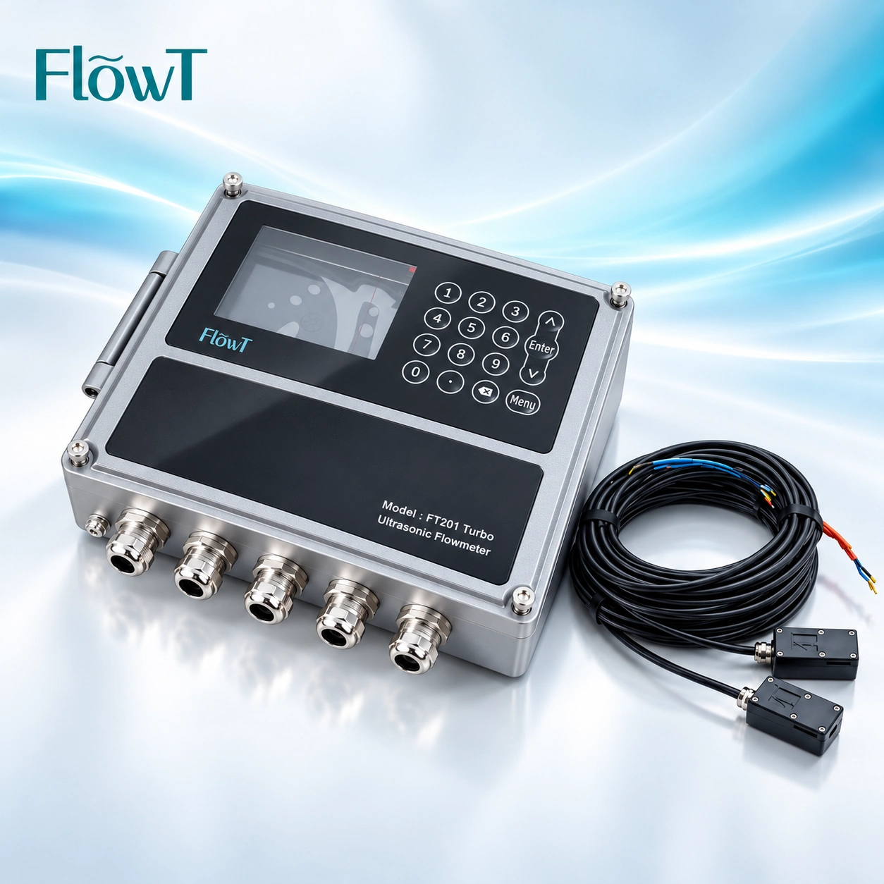
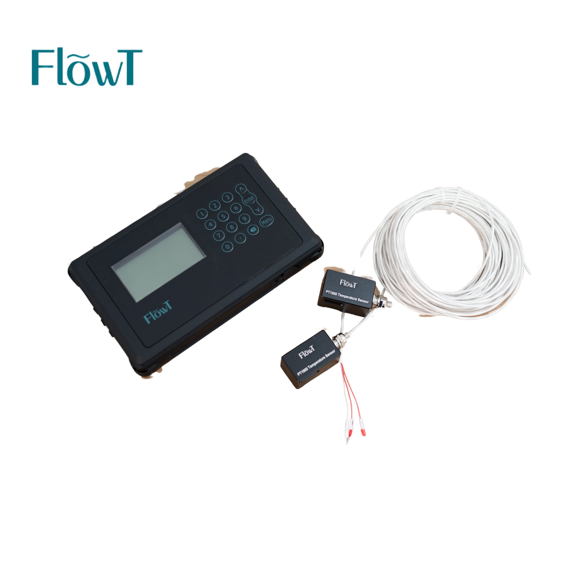
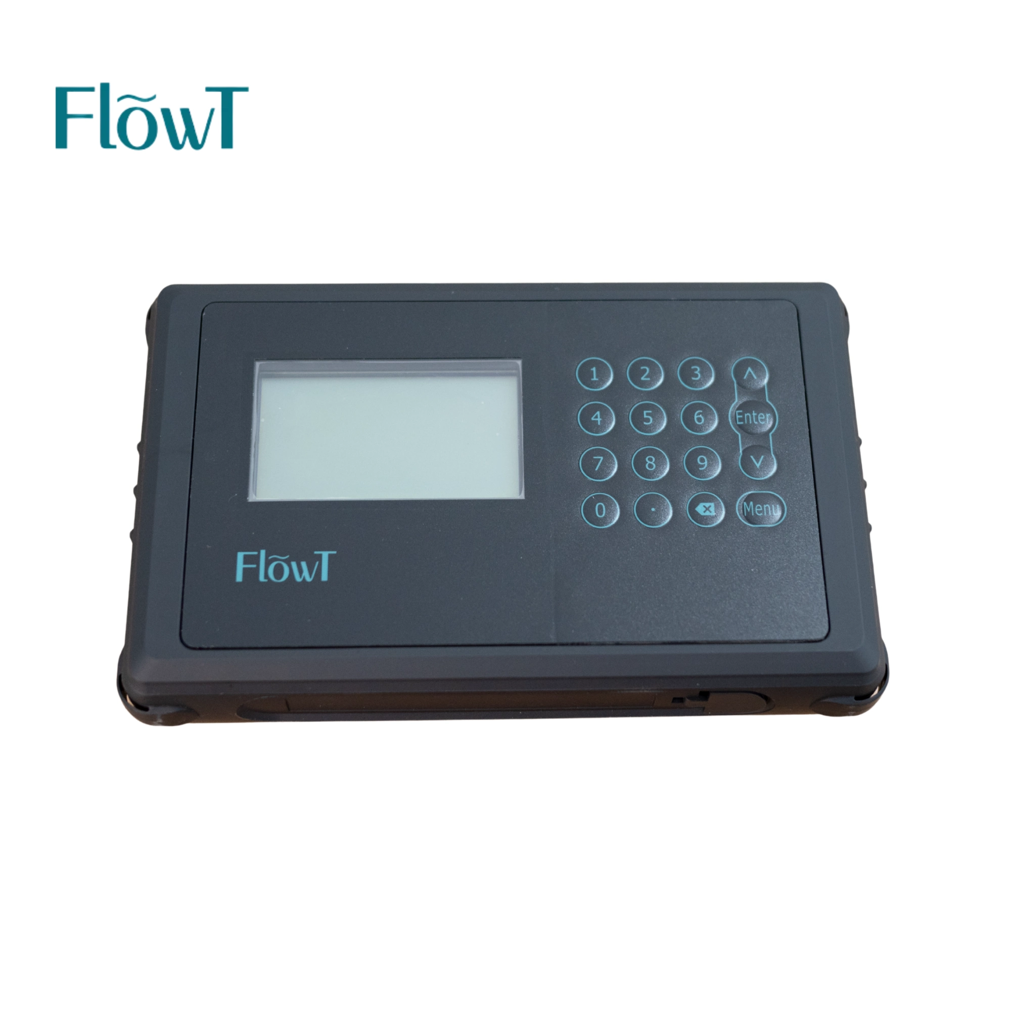
FLOWT / PORTABLE LIQUID FLOW MEASUREMENT
Portable Digital Ultrasonic Flow Meter
Take flow measurement to the pipe. The FT221 combines a portable transmitter, external clamp-on transducers and a mounting arrangement for temporary liquid-flow checks and surveys.
Use it to gather additional flow information, compare readings under controlled conditions or record a changing operating pattern without installing an in-line meter body.
The published configuration lists 25–1200 mm pipe coverage, a rechargeable battery and SD card data storage. Select the sensor set for the actual pipe and liquid.

FIELD GUIDE / 01
Start with the Measurement Task
Check a measurement point
Compare operating readings
Survey a changing process
FIELD GUIDE / 02
Choose the Sensor Around the Site
The FT221 product data gives a 25–1200 mm pipe range. Match the transducer set and mounting arrangement to the pipe, rather than assuming one sensor pair covers every installation.
For a pipe outside the published range, request written confirmation of a suitable configuration and its measurement limits before specifying the meter.
Pipe construction
Outside diameter, material, wall thickness, lining and internal condition affect the acoustic path and the entered geometry.
Liquid conditions
Confirm liquid type, temperature and the presence of bubbles or suspended material. A usable acoustic signal and a full pipe are essential.
Measuring location
Review access, straight pipe, nearby pumps and valves, surface condition and the space needed for the sensor mounting arrangement.
FIELD GUIDE / 03
Technical Data for the Published FT221 Configuration
Sensor choice, installation and operating conditions determine how the instrument performs at the measuring point.
| Model / medium | FT221 / single-medium liquid |
|---|---|
| Pipe range | 25–1200 mm; select the appropriate sensor configuration |
| Flow velocity | Bidirectional: ±0.01 to ±12 m/s |
| Accuracy | ±1% of measured value |
| Display / operation | 240 × 128 backlit LCD / digital keys |
| Front dimensions | 220 × 142 mm; request the full dimensional drawing for enclosure depth and installation planning |
| SD storage / interval | 16 GB / selectable interval 1–99999 seconds |
|---|---|
| Analog output | 4–20 mA; maximum load 750 Ω |
| Communication | RS485 Modbus |
| Battery | Rechargeable lithium battery, 3000 mAh |
| Listed temperatures | Transmitter: −40 to +60 °C; transducer: −40 to +80 °C |
| Humidity | Up to 99% RH, non-condensing |
Battery capacity does not specify operating time. Confirm the required survey duration, charging arrangement, selected sensors and applicable temperature limits with the ordered kit.
Request the Configuration & Quote →
FIELD GUIDE / 04
Prepare, Mount and Confirm the Reading

Make the Installation Repeatable
Identify a location that stays full of liquid and provides a representative flow profile. Review nearby bends, pumps and valves, and use the straight-length guidance for the selected FlowT configuration.
Record the pipe data, clean the mounting area and use the recommended coupling material. Position and secure the sensors at the spacing specified for the installation.
The shown mounting tracks and straps help position the transducers. Confirm the correct track, fixing method and sensor set before the site visit.
Check the Signal Before Using the Result
Verify the entered pipe dimensions, liquid information, selected units and sensor arrangement. Check that the instrument has an acceptable signal and a stable reading for the task.
When a reading changes unexpectedly, review coupling, full-pipe conditions, bubbles and sensor alignment before changing settings. Record any diagnostic information available on the instrument.
Moving the equipment to another pipe creates a new setup. Re-enter and verify the site-specific data rather than carrying the previous settings forward unchanged.

FIELD GUIDE / 05
Plan the Recording Interval Around the Question
The published FT221 configuration includes 16 GB SD storage and a selectable recording interval of 1–99999 seconds. A useful survey needs both a suitable logging setup and enough information about what was happening at the site.
| Before the survey | Measurement-point ID, date and time, pipe dimensions, liquid conditions, sensor set and the purpose of the check |
|---|---|
| During the survey | Flow units, recording interval, observation period, operating changes and any signal or reading instability |
| After the survey | Saved data identification, site photographs, configuration notes and the conditions under which the results were obtained |
A shorter interval produces more observations and should suit the process being investigated. Confirm the available data fields, file format, card handling and any transfer or analysis software before ordering; do not assume USB, wireless or cloud functions from the presence of SD storage.
FIELD GUIDE / 06
Compare Readings Under the Same Conditions
A field comparison is a starting point for investigation
Use consistent engineering units and a defined observation period. Note the position of both measuring points, the operating state of pumps and valves, and whether flow was stable during the comparison.
A difference between readings does not by itself prove that either instrument is out of calibration. Evaluate the installation, measurement uncertainty and operating conditions of both instruments before drawing conclusions.
For commissioning, record the accepted setup and the process condition used as a baseline. For temporary investigations, state what the survey can answer and whether additional pressure, temperature or equipment information is needed.
FIELD GUIDE / 07
Match the Output to the Receiving Equipment
4–20 mA connection
The listed output has a maximum load of 750 Ω. Agree the assigned measurement, flow unit, scaling and wiring with the receiving system; verify the remote value against the local indication.
RS485 Modbus connection
Confirm the applicable connection details, communication settings, register map and data interpretation for the ordered configuration. A communication interface is separate from the procedure for retrieving SD records.
FIELD GUIDE / 08
Specify BTU Measurement as an Option
OPTIONAL ENERGY CONFIGURATION
Flow and Temperature Need to Be Specified Together
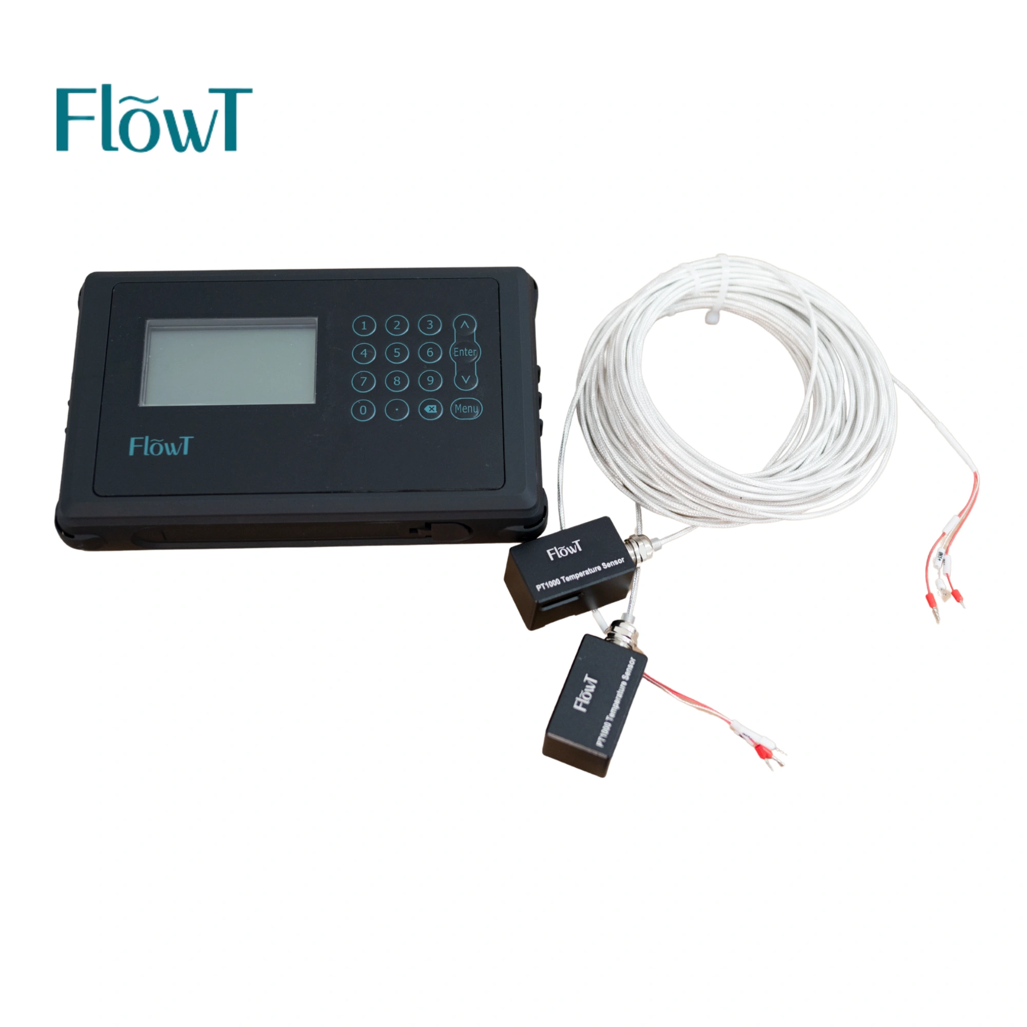
BTU measurement is available as an option. The temperature sensors shown here are PT1000 accessories, separate from the ultrasonic flow transducer pair.
For an energy-measurement enquiry, provide the circuit, liquid, flow range and supply/return temperatures. Ask FlowT to confirm the compatible temperature sensors, their mounting method, required fluid settings and the enabled calculation functions.
The standard flow-measurement enquiry should not assume that the temperature accessories or BTU function are included. Confirm them explicitly in the quotation.
FIELD GUIDE / 09
Where a Portable Survey Can Add Useful Information
Water distribution and utility lines
Obtain additional information at suitable full water pipes where temporary external measurement is practical. Review pipe condition and the acoustic path before committing to the survey.
Cooling and building water circuits
Investigate water-flow behaviour around pumps, branches or cooling equipment within the selected temperature limits. Distinguish a flow survey from a separately configured energy measurement.
Industrial process support
Use a planned measurement to help investigate suitable liquid lines. For chemicals, fuels or other process liquids, submit the actual composition and operating conditions rather than assuming universal compatibility.
Browse the FlowT ultrasonic flow meter range for other instruments, or discuss a site-specific flow measurement solution when a permanent installation or different measurement method is needed.
FIELD GUIDE / 10
Confirm the Portable Kit Before the Site Visit
One measurement plan. A clearly defined kit.
Plan the kit around the transmitter, one transducer pair, the selected ST or DT mounting-track set, pipe straps, coupling compound, charger, output cable, tape measure and carrying case. Agree the exact supplied items and quantities in the quotation.
Instrument and power
Confirm the FT221 version, battery/charger arrangement and the planned operating period. Request an operating-time assessment for the intended logging and site conditions.
Sensors and mounting
Match the sensor range and temperature capability to each pipe. Confirm the chosen ST or DT track, fixing method, cable reach and access requirements; images of alternative arrangements do not mean every set is included.
Data and optional functions
Agree storage and retrieval requirements, analog or communication use, and any BTU accessories or software requested for the project.
FIELD GUIDE / 11
Questions to Resolve Before Ordering
Which pipe diameters are covered?
The published FT221 configuration covers 25–1200 mm with an appropriate sensor selection. For a pipe outside that range, ask FlowT to confirm a suitable instrument and sensor configuration, together with its applicable limits.
Does clamp-on installation require cutting the pipe?
The ultrasonic transducers mount on the pipe exterior and do not require sensor-side pipe penetration. Site access, insulation, surface preparation and safe installation arrangements still need to be planned.
Can it measure any liquid?
No single configuration should be assumed suitable for every liquid. Provide composition, temperature, bubbles, suspended material and pipe construction so the acoustic conditions can be reviewed.
How long can it run on the battery?
The rechargeable battery capacity is specified as 3000 mAh. Confirm the required survey duration and request an operating-time assessment and power plan for the ordered logging setup and site conditions.
Is a comparison with another meter a calibration?
A comparative field reading can reveal a difference, but calibration needs an appropriate reference and a defined procedure. Record conditions and assess both instruments before making a performance conclusion.
Is the BTU option included with the flow kit?
It must be specified separately. Confirm the enabled function, temperature sensors and their mounting, fluid settings and the complete scope of supply.
FIELD GUIDE / 12
Send the Site Data for a Practical Proposal
| Pipe and access | Outside diameter, material, wall thickness, lining, insulation and photos of the proposed measuring point |
|---|---|
| Liquid and operation | Liquid type, temperature, expected flow/velocity range and any gas or suspended material |
| Measurement objective | Spot check, comparison or logging; number of points, observation period and required interval |
| Kit and integration | Sensor/mounting needs, power plan, cable requirements, data retrieval, 4–20 mA or RS485 use and any BTU option |
Prepare the Kit Before the Measurement Day
Share the site information and the result you need. Ask FlowT to confirm the sensor set, mounting arrangement, recording setup and supplied accessories for the job.
Request a Portable Measurement Kit →
Use the FlowT enquiry page for project details and supporting drawings.
Hot Tags: FT221 portable ultrasonic flow meter, digital liquid flowmeter, clamp-on water flow meter, portable flow data logger, ultrasonic flow survey meter, ultrasonic liquid flow meter, non invasive ultrasonic flow meter, ultrasonic flow meter for mining, ultrasonic flow meter for fire protection, ultrasonic flow meter for flow measurement in ducts, ultrasonic flow meter for flow measurement of gases